Terminal applicator apparatus, system, and method

a terminal applicator and terminal technology, applied in the field of terminal applicators, can solve the problems of inability to fully realize cost savings, and inability to use hand tools for medium to high speed/volume production

Inactive Publication Date: 2007-04-12
CRIMPTRONIX
View PDF25 Cites 35 Cited by
  • Summary
  • Abstract
  • Description
  • Claims
  • Application Information

AI Technical Summary

Benefits of technology

[0028] The applicator of the present invention provides several advantages, including:
[0030] 2. The reduction in costs to lease or own applicators as a result of the reduced functionality of the applicator and the opportunity to easily interchange unique parts.

Problems solved by technology

However, given the labor intensity and time consuming nature of this manual process, the use of hand tools is not suitable for medium to high speed / volume production.
The costs associated with owning or leasing these applicators is a major contributor to the overhead costs for the business.
In practice, however, the cost savings was never fully realized.
Shortcomings of these prior art interchangeable applicators were based in part because little to no improvements were made to the terminal feed mechanism.
A large number of base applicators were therefore required to solve this problem, thereby defeating the goal of using one (or a few) base applicators and eroding any cost savings that was otherwise achievable.

Method used


Image

  • Terminal applicator apparatus, system, and method
  • Terminal applicator apparatus, system, and method
  • Terminal applicator apparatus, system, and method

Examples


Embodiment Construction

Terminal Assembly

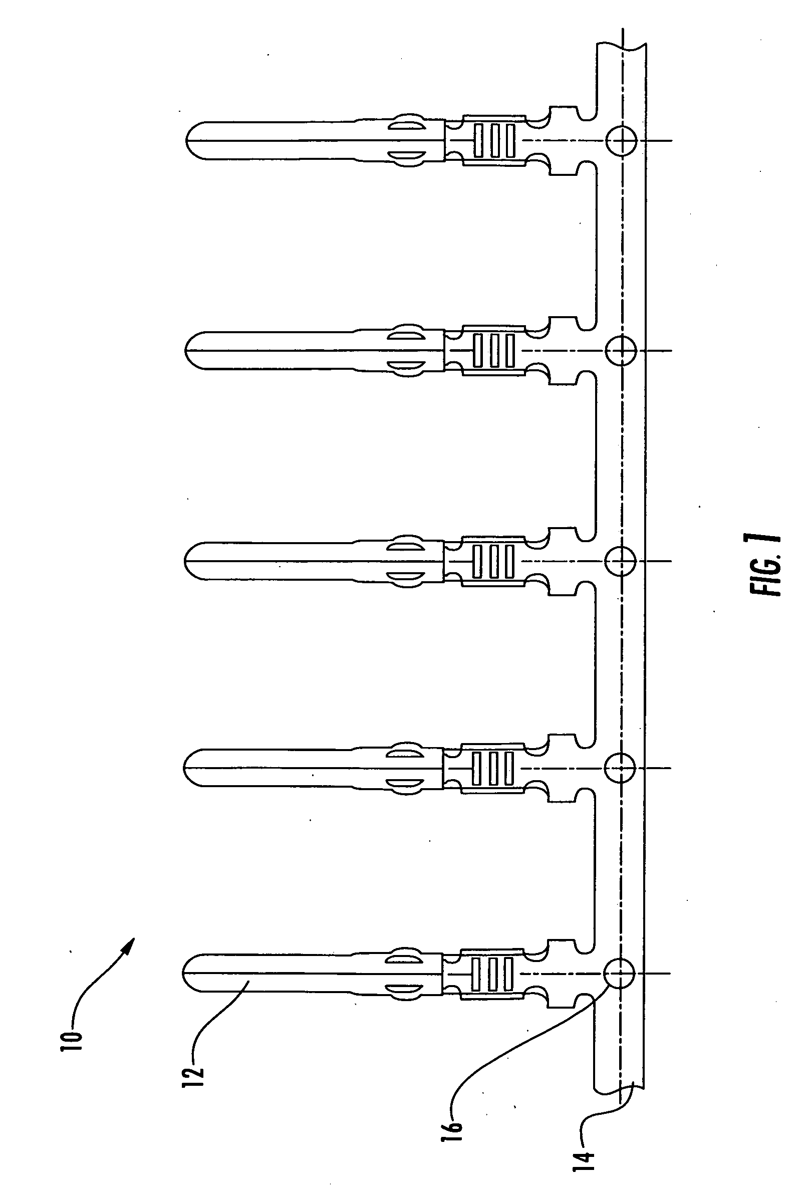
[0055] Referring now to FIG. 1, a typical packaged terminal assembly shown generally as 10, is of the type that can be used in the applicators of the present invention. Terminal assembly 10 is known in the art to support the feeding of individual terminals 12 into applicators. It is understood that terminals 12 can comprise open barrel terminals, closed barrel terminals, or any other terminal known to those of skill in the art. Many terminals 12 can be attached to a single, continuous terminal carrier strip 14 and in some cases, many thousands of terminals 12 can be produced on one terminal carrier strip 14. Terminal carrier strip 14 can comprise a plurality of feed holes 16 wherein at least one feed hole 16 is provided for each terminal 12. Each feed hole 16 can also be precisely positioned with respect to an individual terminal 12 and can be used to facilitate the manufacturing process of terminals 12. As is known in the art, feed mechanisms in applicators can al...


PUM

PropertyMeasurementUnit
rotationaaaaaaaaaa
pressureaaaaaaaaaa
sizesaaaaaaaaaa

Abstract

Apparatuses, systems, and methods are provided for automatically crimping terminals or connectors to wires wherein the terminals or connectors are provided in strip form and may be of varying sizes, shapes, and pitches. An apparatus according to the present invention includes an applicator body and a ram movably mounted in relation to the body and drivable in a first path through a working stroke towards, and a return stroke away from, a crimping anvil. The apparatus further includes a crimping die on the ram for cooperation with the anvil and adapted to crimp a terminal connector located therebetween onto a wire during each working stroke of the ram. The apparatus additionally includes a drive mechanism adapted to contact the strip through pressure engagement and to feed the strip along a second path to locate the leading connector on the strip between the anvil and the die.

Description

CROSS-REFERENCE TO RELATED APPLICATIONS [0001] This application is related to U.S. Provisional Patent Application Serial No. 60 / 724,430, filed Oct. 7, 2005 and U.S. Provisional Patent Application Serial No. 60 / 758,084 filed Jan. 12, 2006; the disclosures of which are incorporated by reference in their entirety.BACKGROUND OF THE INVENTION [0002] 1. Technical Field [0003] The invention disclosed herein relates generally to electrical terminal applicators, and more particularly to providing terminal applicator apparatuses, systems, and methods for automatically crimping terminals or connectors to wires wherein the terminals or connectors are provided in strip form and may be of varying sizes, shapes, and pitches. [0004] 2. Background Art [0005] As is known in the art, a wide range of electronic and electrical products use crimp terminals to make electrical connections from wires to other wires, printed circuit boards or other components. Generally, a crimp terminal consists of three se...

Claims


Application Information

Patent Timeline
Patent Type & Authority Applications(United States)
IPC IPC(8): B23P19/00
CPCH01R43/055Y10T29/49174Y10T29/5149Y10T29/5193Y10T29/53213Y10T29/49181Y10T29/532Y10T29/49185Y10T29/53235Y10T29/53261Y10T29/5327Y10T29/53226Y10T29/53209
Inventor GARNER, WESLEY THOMAS JR.
Owner CRIMPTRONIX
Why Eureka
Try Eureka