
Device for absorbing carbon dioxide, and a method for absorbing carbon dioxide

a technology of carbon dioxide and absorbing device, which is applied in the direction of arsenic compounds, silicon compounds, separation processes, etc., can solve the problems of many islands and properties being submerged, and the earth's ecology affecting the creatures including humans

Inactive Publication Date: 2005-03-15
INT ENVIRONMENTAL CONSERVATIVE ASSOC
View PDF21 Cites 31 Cited by
  • Summary
  • Abstract
  • Description
  • Claims
  • Application Information

AI Technical Summary

Benefits of technology

The device effectively reduces CO2 concentrations in exhaust gases, contributing to mitigating global warming by utilizing a cement composition that efficiently absorbs CO2, with specific optimal compositions of CaO, SiO2, Al2O3, Fe2O3, MgO, Na2O, and SO3, demonstrating significant CO2 absorption capabilities as shown in examples with automobile and factory exhaust applications.

Problems solved by technology

If it continues, the icebergs in the south and north poles will be melted, significantly raising the sea level, resulting in the submerging of many islands and properties.
In addition, the concomitant breakdown of the Earth's ecology would affect the creatures including human beings.

Method used


Image

  • Device for absorbing carbon dioxide, and a method for absorbing carbon dioxide
  • Device for absorbing carbon dioxide, and a method for absorbing carbon dioxide
  • Device for absorbing carbon dioxide, and a method for absorbing carbon dioxide

Examples


example 1

As the carbon dioxide absorbing material, the following cement composition was provided.CaO in an amount of 60 to 67% by weight,SiO2 in an amount of 17 to 25% by weight,Al2O3 in an amount of 3 to 8% by weight,Fe2O3 in an amount of 0.5 to 6% by weight,MgO in an amount of 0.1 to 5.5% by weight,Na2O and / or K2O in an amount of 0.5 to 1.3% by weight, andSO3 μl an amount of 1 to 3% by weight.

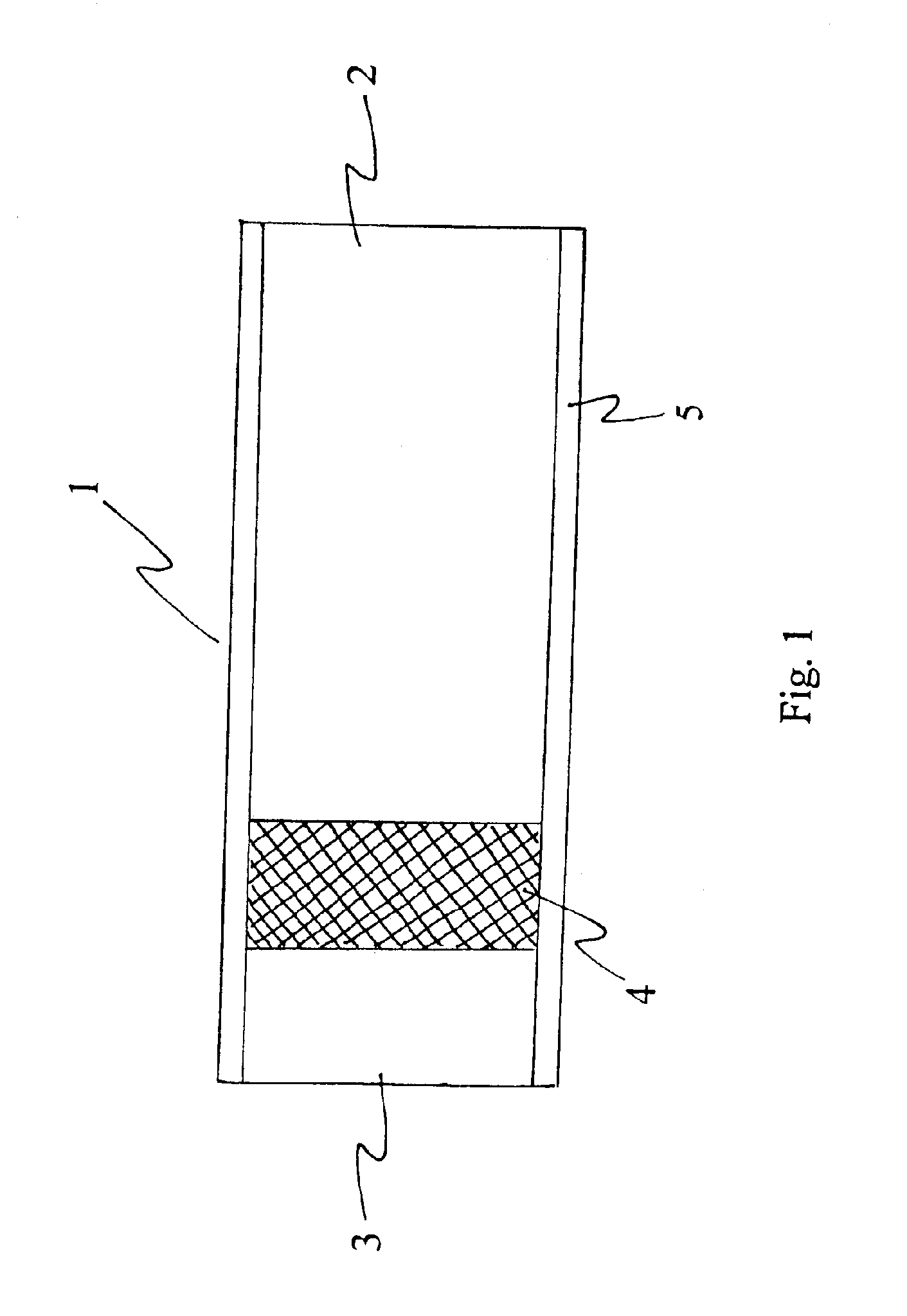
The cement composition was in the form of powder. The cement composition was enclosed in a net having a mesh smaller than the average particle size of the cement composition.

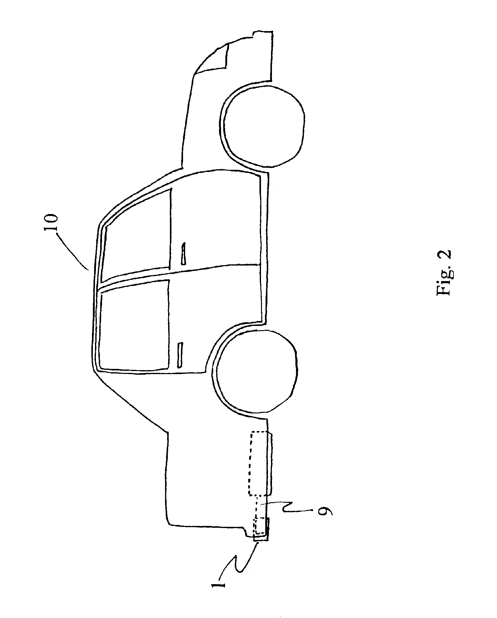
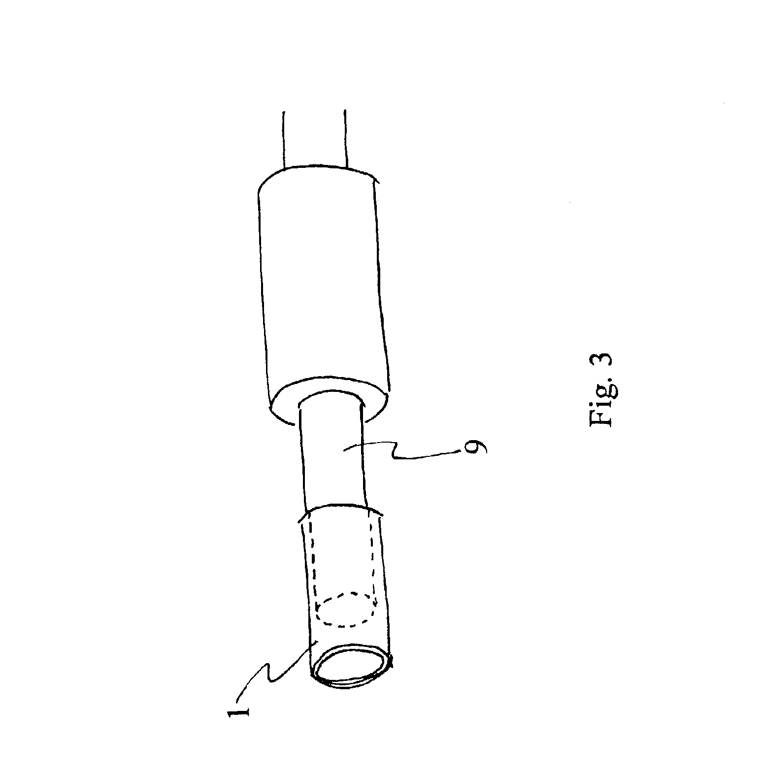
The net including the cement composition prepared in Example 1 was placed inside a pipe to form a device to absorb carbon dioxide according to the present invention. Then, the device was equipped at the end of an exhaust pipe of an automobile.

example 2

The net including the ceramic composition prepared in Example 1 was placed inside a pipe to form a device to absorb carbon dioxide according to the present invention. Then, the device was equipped at the end of an exhaust pipe of an automobile.

The amount of the discharge of carbon dioxide was measured. The result proved that the device of the present invention could absorb carbon dioxide and significantly decrease the concentration of carbon dioxide in the discharged exhaust gas.

example 3

The net including the cement composition produced in Example 1 was placed inside a pipe to form to absorb carbon dioxide according to the present invention. Then, the device was equipped of chimney of a chemical factory.

The amount of the discharge of carbon dioxide was measured. The result proved that the device of the present invention could absorb carbon dioxide and significantly decrease the concentration of carbon dioxide in the discharged exhaust gas.


PUM

PropertyMeasurementUnit
particle sizeaaaaaaaaaa
thicknessaaaaaaaaaa

Abstract

The present invention relates to a device for absorbing carbon dioxide, which is equipped along an automobile exhaust pipe and a factory chimney. The present invention also relates to a method for absorbing carbon dioxide. According to the present invention, there is provided a device for absorbing carbon dioxide, comprising a housing 4 of a material having air permeability; a cement composition for absorbing carbon dioxide, enclosed inside the housing 4; and a pipe 5 across the housing, the pipe having an inlet 2 and an outlet 3. According to the present invention, when a gas is introduced from the inlet 2, carbon dioxide in the gas is absorbed by the carbon dioxide absorbing materials such as a cement composition enclosed in the housing 4. The gas is discharged from the outlet 3.

Description

BACKGROUND OF THE INVENTIONThe present invention relates to a device for absorbing carbon dioxide, which may be equipped on an automobile exhaust pipe or a factory chimney. The present invention also relates to a method for absorbing carbon dioxide.RELATED ARTThe stemming of the warming of the Earth is one of the most difficult objectives to be solved. The average temperature of the Earth has been recently rising gradually. If it continues, the icebergs in the south and north poles will be melted, significantly raising the sea level, resulting in the submerging of many islands and properties. In addition, the concomitant breakdown of the Earth's ecology would affect the creatures including human beings. The cause of the warming of the Earth is said to be the recent increase of the amount of carbon dioxide discharged.The objectives of the present invention are to absorb carbon dioxide and to reduce its amount discharged, resulting in contributing to stem the warming of the Earth.SUMM...

Claims


Application Information

Patent Timeline
Patent Type & Authority Patents(United States)
IPC IPC(8): B01D53/02B01D53/62
CPCB01D53/02B01D53/62Y02C10/04Y02A50/20Y02C20/40B01D53/04
Inventor MITSUDA, HISATERU
Owner INT ENVIRONMENTAL CONSERVATIVE ASSOC
Learn More