Cable extension for reducing EMI emissions

a technology of emi and cable extension, which is applied in the direction of cables, insulated conductors, conductors, etc., can solve the problems of undesirable signals, emi can arise in any electronic system, and create problems in various systems

a technology of emi and cable extension, which is applied in the direction of cables, insulated conductors, conductors, etc., can solve the problems of undesirable signals, emi can arise in any electronic system, and create problems in various systems

US6867362B2Inactive Publication Date: 2005-03-15HEWLETT PACKARD DEV DEV CO +2

Image

  • Cable extension for reducing EMI emissions
  • Cable extension for reducing EMI emissions
  • Cable extension for reducing EMI emissions

Examples


Embodiment Construction

)

What is desired is an EMI solution that allows usage of an existing cable infrastructure while complying with global standards for radiated emissions.

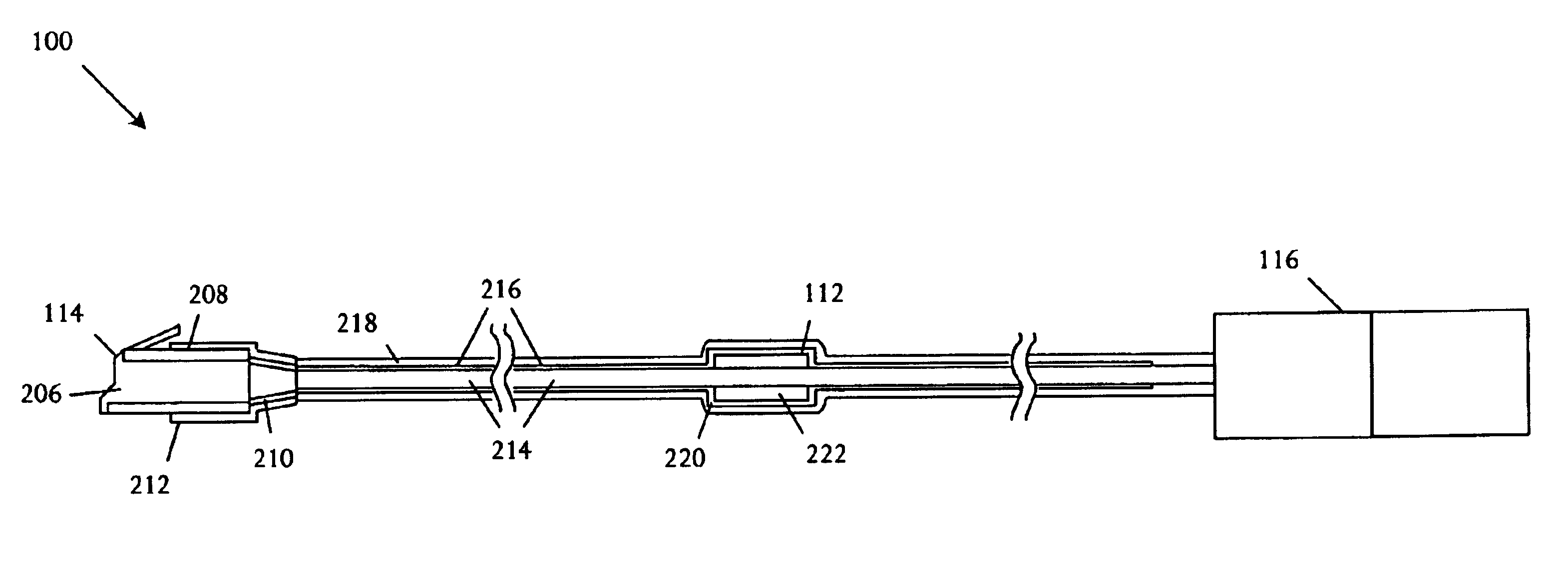
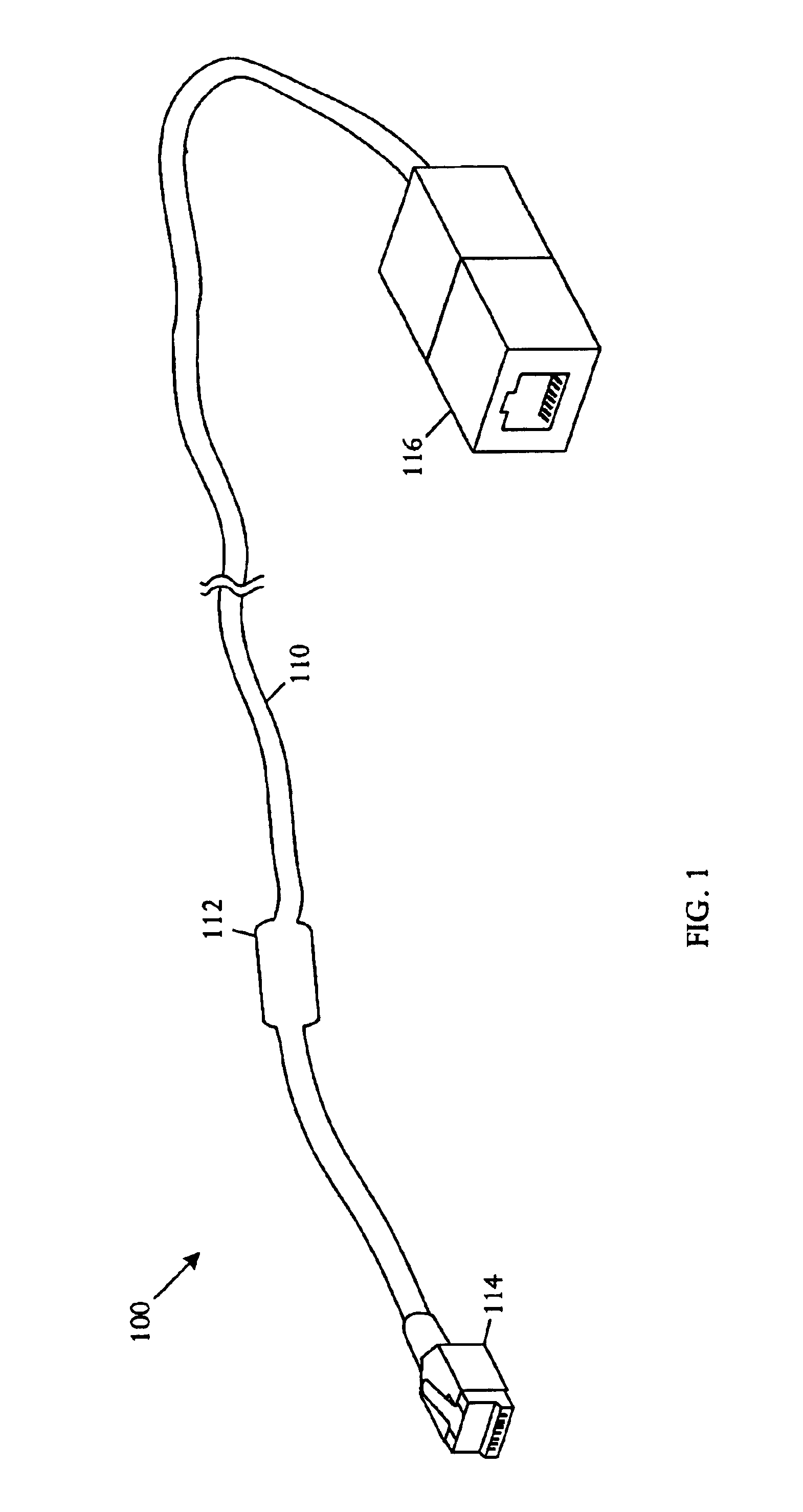
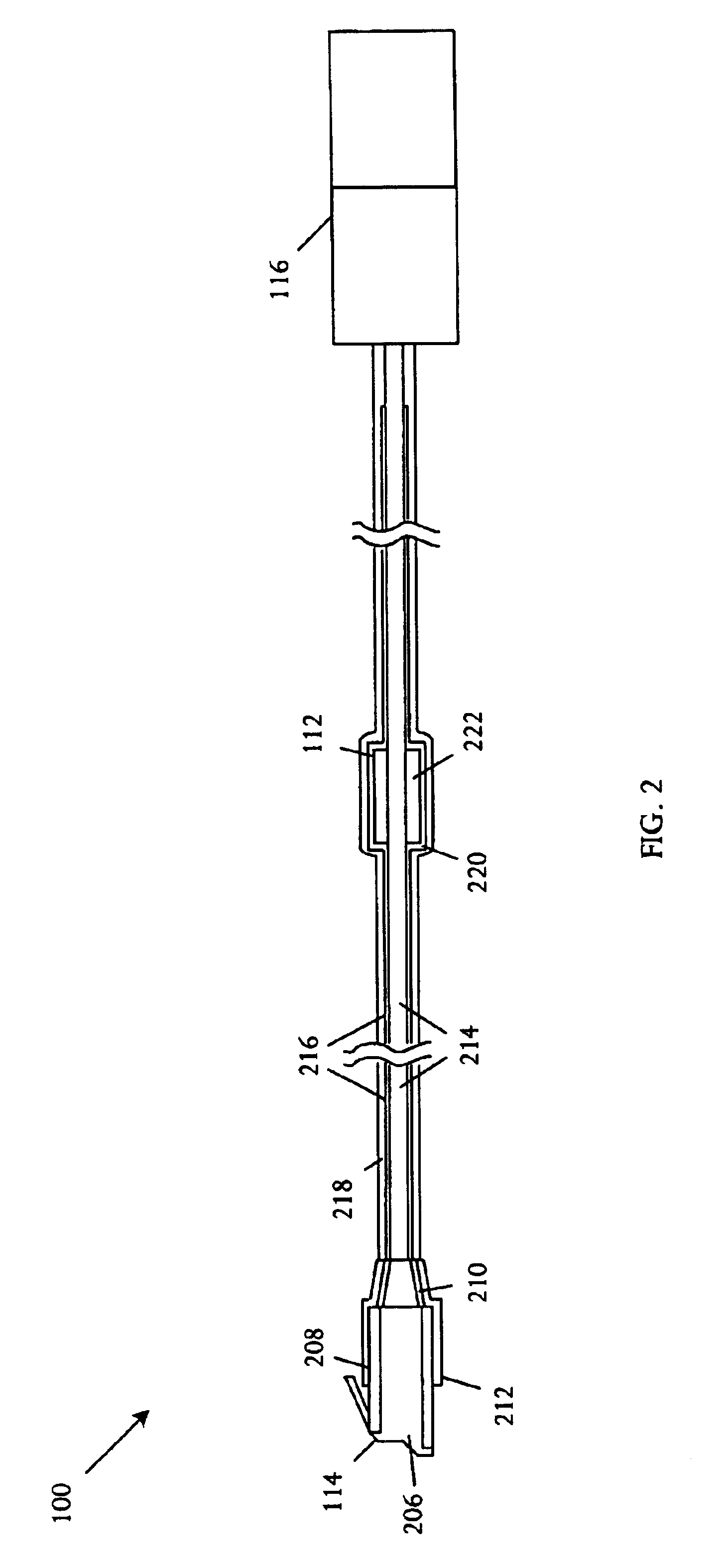
A cable extension can be coupled between a communicating device and a communication cable to eliminate or substantially reduce radiated emissions. In specific embodiments a local area network (LAN) cable extension can be coupled between a LAN device and a LAN cable to control EMI emissions. The cable extension comprises a cable with a first connector capable of coupling proximal to the communicating device and a second connector capable of coupling to the communication cable. A filter encases or surrounds the cable at a position between the first and second connectors. A cable shield encases or surrounds the filter and the cable in vicinity not encased by the filter. The first connector is shielded and couples to the cable shield. The second connector is isolated from the cable shield. The extension cable can be any length that attenu...


PUM

PropertyMeasurementUnit
distanceaaaaaaaaaa
distanceaaaaaaaaaa
distanceaaaaaaaaaa

Abstract

A cable emission reduction apparatus includes a conductive cable core, a filter, and a cable shield. The conductive cable core extends longitudinally from a first end to a second end. The filter is coupled to and encases the conductive cable core, and extends longitudinally only a portion of the conductive cable core length, positioned between the first end and the second end. The cable shield is coupled to and encases the conductive cable core and the filter. The cable shield extends longitudinally from the first end over the filter and terminating prior to the second end.

Description

BACKGROUND OF THE INVENTIONElectromagnetic interference (EMI) can arise in any electronic system, either directly from circuitry or indirectly by conduction along connecting cables and by radiation. EMI can also arise from external sources to create problems in various systems. Undesirable signals occur whenever interference has a source, a receiver, and a transfer path. Accordingly, EMI can be reduced or eliminated by suppressing interference at the source, protecting the receiver against interference, and by reducing transmission.Interference can propagate by radiation of electromagnetic waves in free space and by conduction on a conductive pathway. Techniques for suppressing radiant interference include shielding with conductive materials such as conductive adhesive tapes, wire mesh, and gaskets, or absorbing with absorbing materials such as carbon or ferrite-filled binders. Techniques for suppressing conducted interference include usage of ferromagnetic cable absorbers, connecto...

Claims


Application Information

Patent Timeline
15 Mar 2005
Publication
US6867362B2
IPC
H05K9/00; H01R13/719
CPC
H05K9/0066; H01R13/719; H01R2201/04
Inventors
CHERNISKI, ANDREW M.; SMITH, KEVIN