Rotary push switch device

a rotary push switch and switch technology, applied in the direction of mechanical control devices, contact mechanisms, instruments, etc., can solve the problems of disadvantageous operability of the rotary push switch device and the difficulty of pushing operation

Active Publication Date: 2005-03-15
ALPS ALPINE CO LTD
View PDF9 Cites 35 Cited by
  • Summary
  • Abstract
  • Description
  • Claims
  • Application Information

AI Technical Summary

Benefits of technology

A rotary push switch device in one embodiment of the present invention includes a cylindrical rotary push knob that is subjected to push and rotary operations, a rotary type electric part unit rotated by the rotary push knob, a push knob that is subjected to a push operation, and a push switch unit pressed b...

Problems solved by technology

Accordingly, since a knob (key top 13) located at a center has only a push function and a rotary function is provided with only an outside knob (rotary operation member 14), when a push operation i...

Method used


Image

  • Rotary push switch device
  • Rotary push switch device
  • Rotary push switch device

Examples


Embodiment Construction

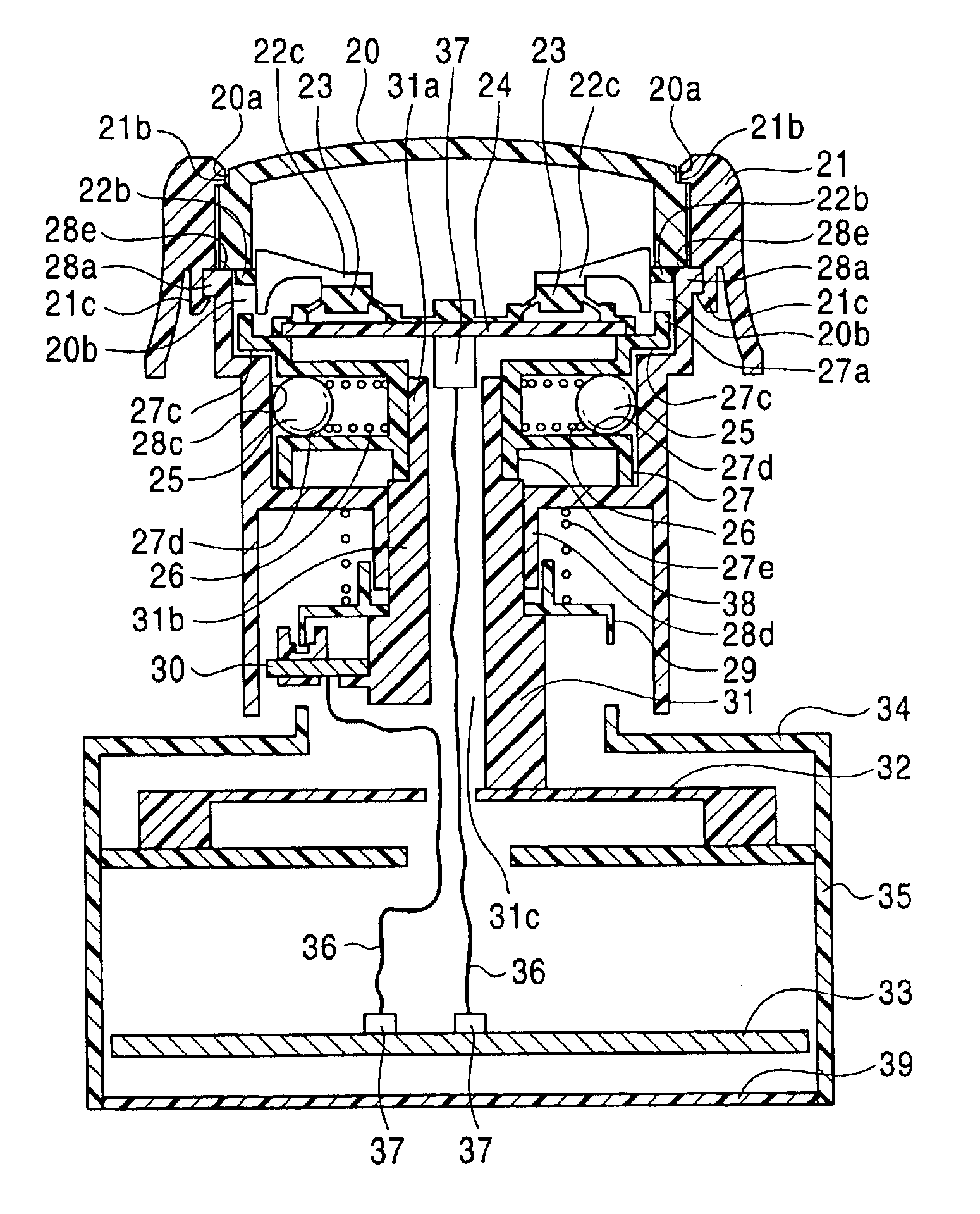
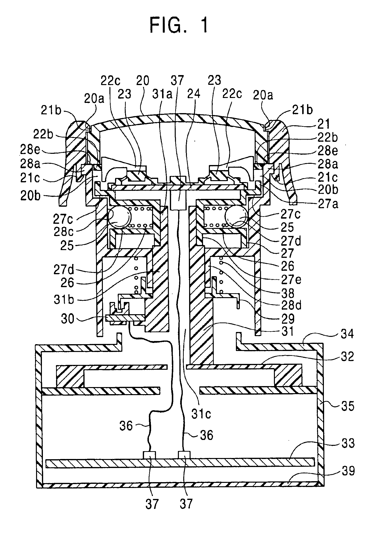
An embodiment of the present invention will be explained with reference to the drawings. FIG. 1 is a longitudinal sectional view of a rotary push switch device according to the embodiment of the present invention, FIG. 2 is a longitudinal sectional view of the rotary push switch device shown in FIG. 1 when it is subjected to a push operation, and FIG. 3 is an exploded perspective view of the rotary push switch device shown in FIG. 1.

As shown in the drawings, the rotary push switch device according to the embodiment is composed of a push knob 20, a rotary push knob 21, a push ring 22, a push rubber contact element 23 that is pushed by the push ring 22, a push substrate 24, which is paired with the push rubber contact element 23 and constitutes a push switch, a hard ball holder 27 for holding hard balls 25 and springs 26, which impart a click feel when a rotary operation is executed, a rotary cam 28, a rotary drive plate 29 for detecting the rotary operation, a sensor substrate 30, wh...


PUM


Abstract

A rotary push switch device includes a cylindrical rotary push knob, which is subjected to push and rotary operations, a rotary drive plate, which is rotated by the rotary push knob, a push knob, which is disposed inwardly of the rotary push knob and pushed, and a push rubber contact element which is pressed by pushing the push knob. When the push knob is subjected to the push operation, the rotary push knob is also pushed in association with the push knob, and when the rotary push knob is subjected to the rotary operation, the push knob is prevented from being rotated in association with the rotary push knob.

Description

This application claims the benefit of priority to Japanese Patent Application No. 2003-031298, herein incorporated by reference.BACKGROUND OF THE INVENTION1. Field of the InventionThe present invention relates to a rotary push switch device that is preferably applied to an input to an air conditioner, a navigator, and the like, which are mounted on a vehicle, and is most suitable when a design is formed at a center.2. Description of the Related ArtThere are many switch devices that employ known technologies and can be subjected to rotary and push operations. For example, various types of electric parts such as rotary switches, push button switches, and the like, which are used in audio systems, air conditioners, and the like, are mounted on vehicles, and these electric parts are operated by drivers and passengers who manually manipulate operation knobs. Among these vehicle-mounted electric parts, there is known a rotary push switch device used in, for example, an audio system. The ...

Claims


Application Information

Patent Timeline
IPC IPC(8): H01H25/06H01H25/00H01H25/04H01H89/00
CPCG05G1/08H01H25/06H01H25/065H01H3/42
Inventor HAYASHI, YUKIHARU
Owner ALPS ALPINE CO LTD
Why Eureka
Try Eureka