Variable gain amplifier circuit

a variable gain amplifier and amplifier circuit technology, applied in the direction of amplifier modification to reduce non-linear distortion, gain control, volume compression/expansion, etc., can solve the problem of difficult to reduce the driving curren

Inactive Publication Date: 2005-03-15
RENESAS ELECTRONICS CORP
View PDF12 Cites 12 Cited by
  • Summary
  • Abstract
  • Description
  • Claims
  • Application Information

AI Technical Summary

Problems solved by technology

Thus, it is difficult to decrease the driving current.

Method used


Image

  • Variable gain amplifier circuit
  • Variable gain amplifier circuit
  • Variable gain amplifier circuit

Examples


Embodiment Construction

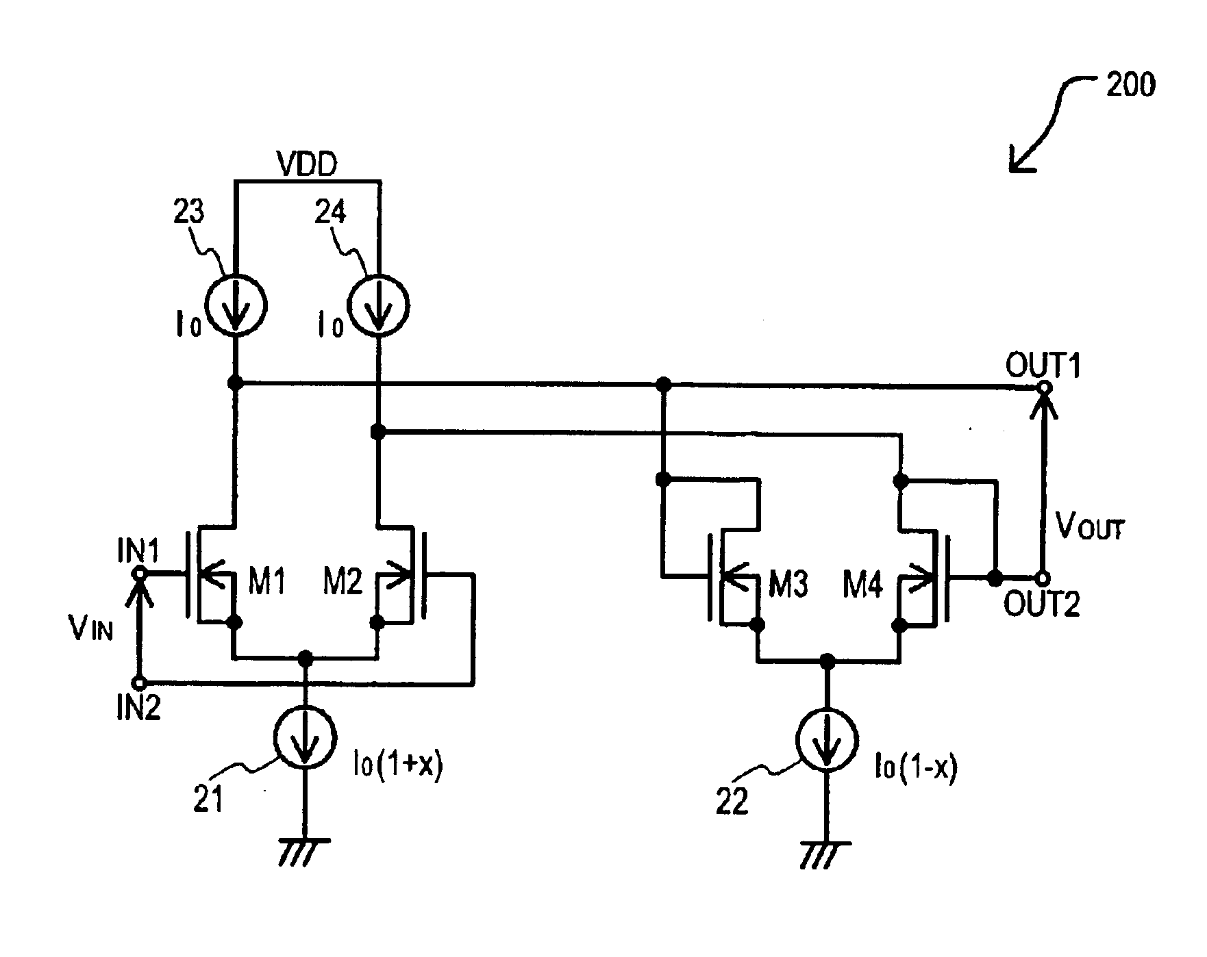
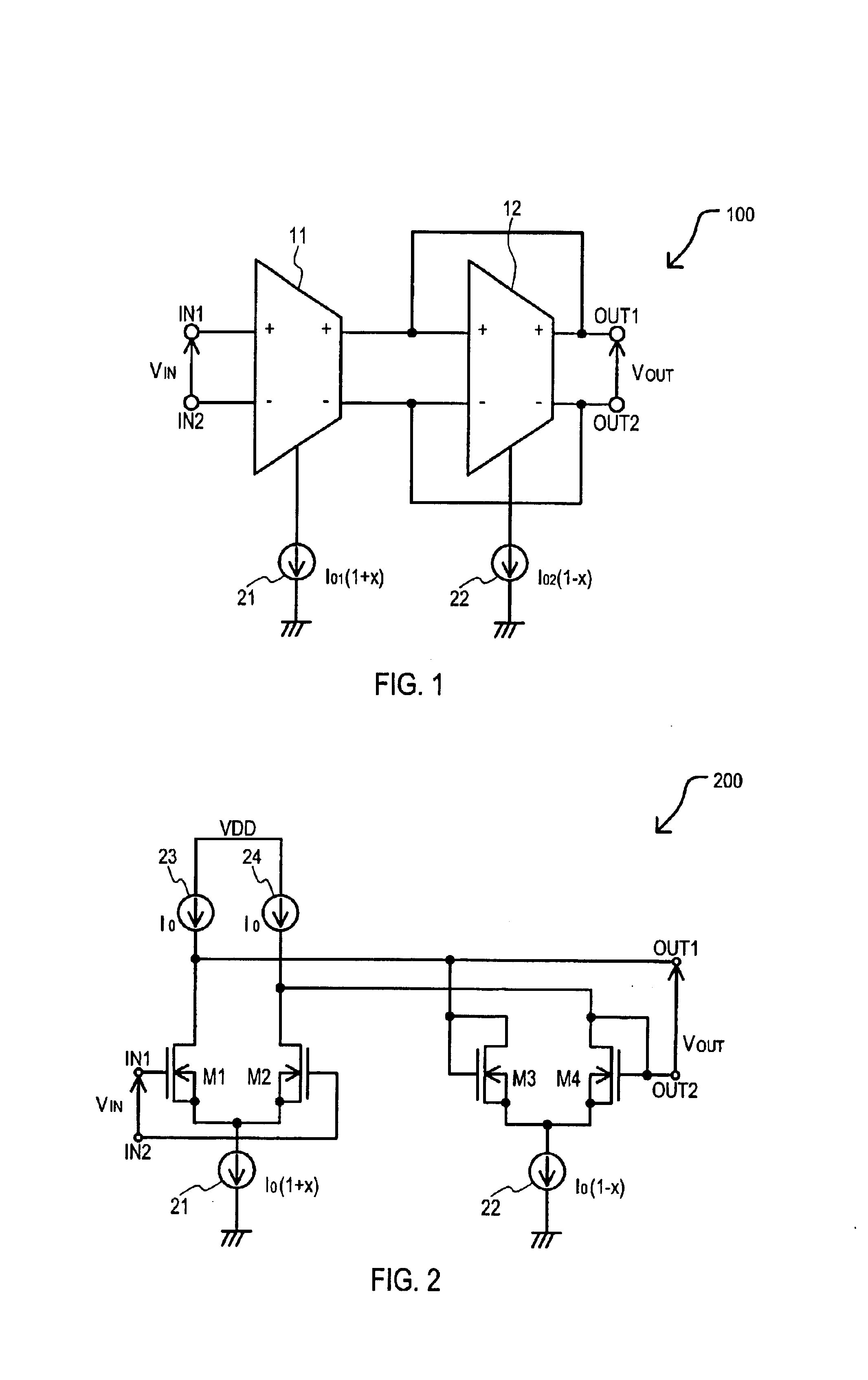
The principle operation of the present invention will first be described. In the invention, the transconductance gm of an OTA (operational transconductance amplifier) may be made almost proportional to the driving current or the square root of the driving current. Accordingly, the driving currents of two OTAs may include variable functions such as 1+x and 1−x, so that the voltage gain of a VGA including two OTAs may be set at GV=1+x1-xorGV=1+x1-x.

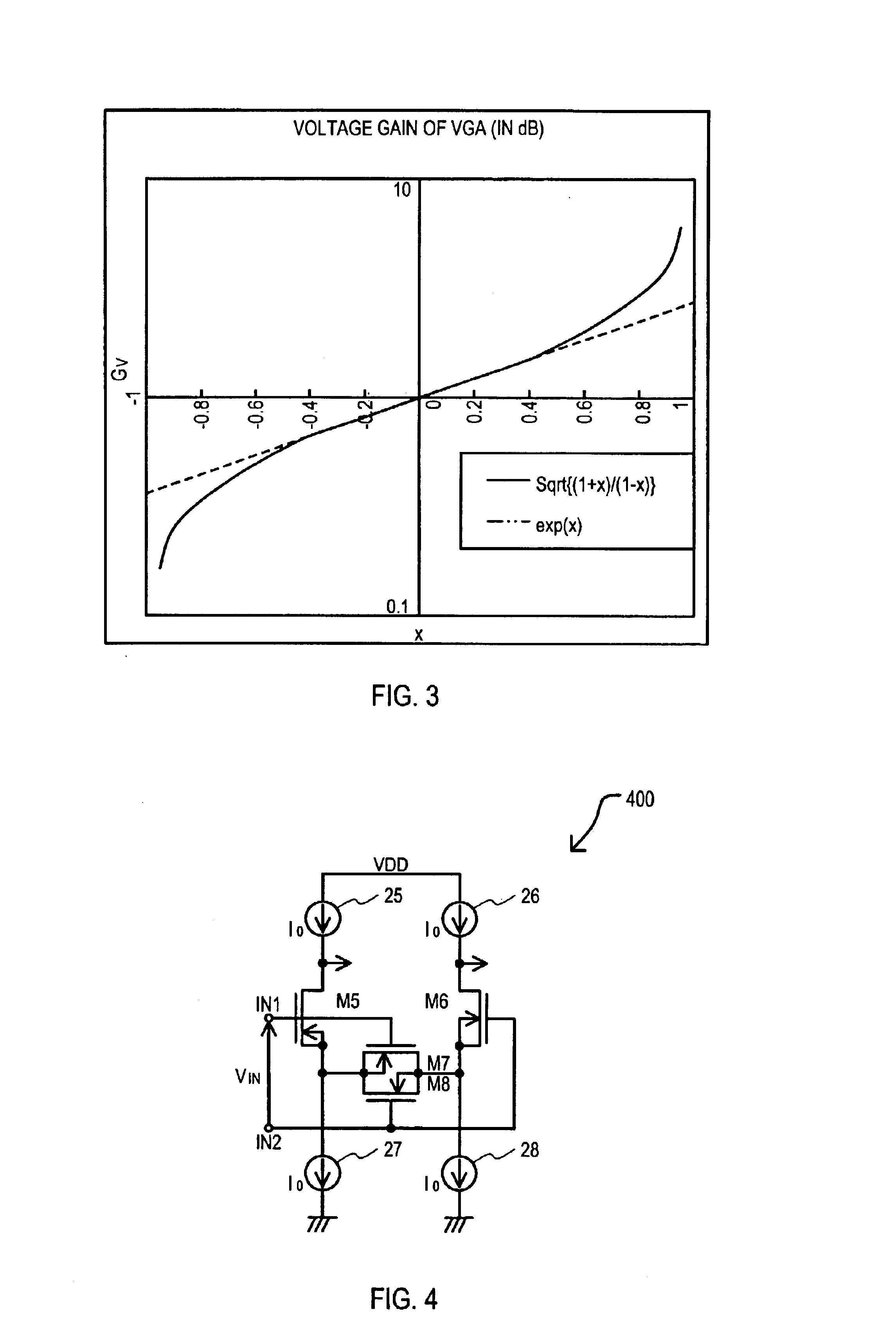
Herein, the approximation may be made such as e2⁢xn≈(1+x1-x)1n.

This function may have an exponential characteristic for x and may approximate the exponential characteristic.

Alternatively, the exponential characteristic can be approximated based on the identity exn={1+tanh⁢(x2)1-tanh⁢(x2)}1n

and the driving currents of the two OTAs may be variable such as 1+tan h(x / a) and 1−tan h(x / a), where a is a constant and whereby the voltage gain of a VGA including two OTAs may be set at GV=1+tanh⁡(xa)1-tanh⁡(xa)orGV=1+tanh⁡(xa)1-tanh⁡(xa).

In this case,...


PUM


Abstract

A variable gain amplifier circuit (100) that may have a gain exponentially changed has been disclosed. A variable gain amplifier circuit (100) may include a first OTA (Operational Transconductance Amplifier) (11) and a second OTA (12). A first OTA (11) may receive a differential voltage at input terminals (IN1 and IN2). A second OTA (12) may receive an output from a first OTA (11) and may provide a differential output voltage at output terminals (OUT1 and OUT2). A second OTA (12) may have second OTA input terminals and second OTA output terminals commonly connected to output terminals (OUT1 and OUT2). A small-signal transconductance of the first and second OTAs (11 and 12) may be proportional to driving currents. A first OTA (11) may have a driving current of I0{1+tan h(x / a)} and a second OTA (12) may have a driving current of I0{1−tan h(x / a)}, where −1<x<1 and a is a constant. In this way, a variable gain amplifier circuit (100) may operate at a low voltage, with a small circuit current, and with essentially no temperature dependence.

Description

TECHNICAL FIELDThe present invention relates generally to a variable gain amplifier circuit and more particularly to a variable gain amplifier circuit formed on a semiconductor integrated circuit that may be operable at a low voltage with small current, may have a gain exponentially changed in response to a control signal, and may have reduced variations due to temperature changes.BACKGROUND OF THE INVENTIONConventional variable gain amplifiers are disclosed in U.S. Pat. No. 5,757,230 (5,757,230) published May 23, 1998 and U.S. Pat. No. 5,886,579 (5,886,579) published Mar. 23, 1999.In general, a variable gain amplifier is abbreviated as a VGA. Up to now, approximation methods of implementing the exponential characteristic have been well-known, including an approximation method using Taylor's expansion. ex≈1+x+12⁢x2(1)and an approximation method using the bilinear transformation ex≈1+x1-x.(2)Referring now to FIG. 16, a graph illustrating the relationship between the true exponential ...

Claims


Application Information

Patent Timeline
Patent Type & Authority Patents(United States)
IPC IPC(8): H03G7/00H03F3/45H03F1/32H03F3/68H03G3/10
CPCH03F1/3211H03F1/3241H03G7/001H03F3/45771H03F2203/45504
Inventor KIMURA, KATSUJI
Owner RENESAS ELECTRONICS CORP
Why Eureka
Try Eureka