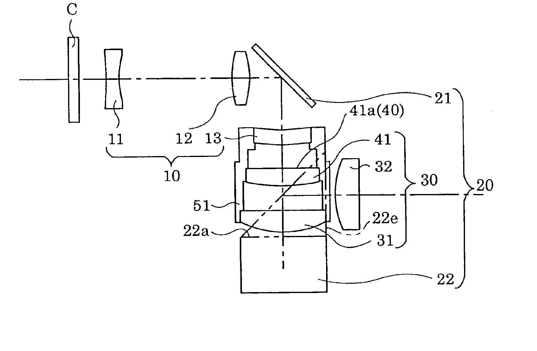
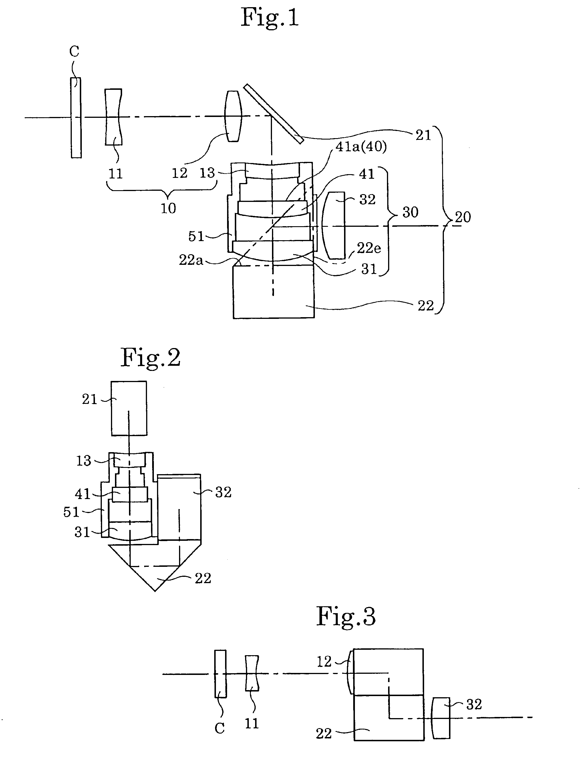
Real-image finder optical system
a real-image finder and optical system technology, applied in the field of real-image finder optical systems, can solve the problems of inconvenient use, shortening the focal length of the objective optical system, and increasing the thickness of the camera, so as to achieve long eye relief and high finder magnification
- Summary
- Abstract
- Description
- Claims
- Application Information
AI Technical Summary
Benefits of technology
Problems solved by technology
Method used
Image
Examples
embodiment 2
[Embodiment 2]
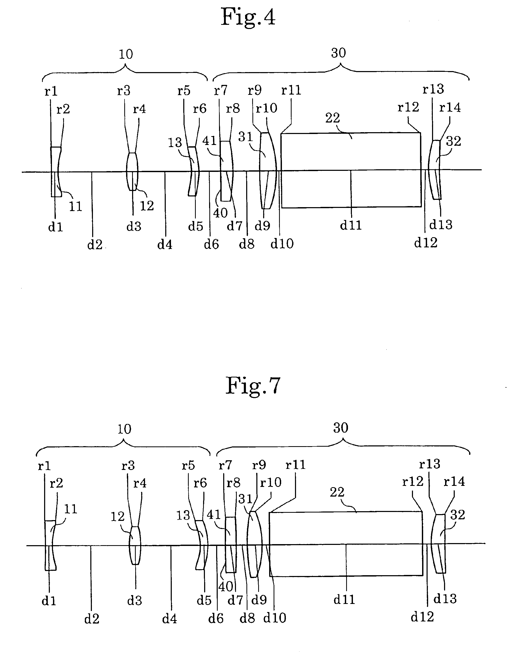
FIG. 7 shows the optical arrangement, according to the second embodiment, in which the reflection surfaces of a real-image finder optical system are shown as developed views. The optical arrangement of the second embodiment is the same as the first embodiment except that (i) surface Nos. 7 and 8 indicates a plane-parallel plate 41′, and (ii) the position where the object image by the objective optical system is formed is the eyepiece-side plane of the plane-parallel plate 41′, i.e., surface No. 8. FIG. 8A through 8D show aberrations, at the short focal length extremity, occurred in the optical arrangement shown in FIG. 7. FIGS. 9A through 9D show aberrations, at the long focal length extremity, occurred in the optical arrangement shown in FIG. 7. Table 2 shows the numerical data of this embodiment.
TABLE 2S.F.L.E.L.F.L.E.Finder Magnification (fo / fe)0.39—1.06Diopter [dptr] = −1.0Surface No.rdNdν1*−30.5801.301.5854729.9210.95313.80-2.680——3*8.0612.101.4917657.44−13.422 10...
embodiment 3
[Embodiment 3]
FIG. 10 shows optical arrangement according to the third embodiment, in which the reflection surfaces of a real-image finder optical system are shown as developed views. The optical arrangement of the third embodiment is the same as the first embodiment except that (i) the positive meniscus third lens element 13 (surface Nos. 5 and 6) is replaced with a negative meniscus lens element having a concave surface facing towards the object, (ii) the eyepiece-side surface (No. 8) of the planoconvex lens element 41 (condenser lens: surfaces Nos. 7 and 8) is the flat surface, and (iii) the position where the object image by the objective optical system is formed is the eyepiece-side plane of the planoconvex lens element 41, i.e., surface No. 8. FIGS. 11A through 11D show aberrations, at the short focal length extremity, occurred in the optical arrangement shown in FIG. 10. FIGS. 12A through 12D show aberrations, at the long focal length extremity, occurred in the optical arrang...
embodiment 4
[Embodiment 4]
FIG. 13 shows the optical arrangement according to the fourth embodiment, in which the reflection surfaces of a real-image finder optical system are shown as developed views. The optical arrangement of the fourth embodiment is the same as the third embodiment except that (i) surface Nos. 7 and 8 indicates a plane-parallel plate 41′, (ii) the position where the object image by the objective optical system is formed is the object-side plane of the plane-parallel plate 41′, i.e., surface No. 7, (iii) on the eyepiece side with respect to the object image, two separate prisms 23 and 24 are provided, i.e., in the prism 23, two reflection surfaces are used, and in the prism 24, one reflection surface is used, and (iv) the eyepiece lens element 32 (surface Nos. 15 and 16) is a planoconvex lens element. FIGS. 14A through 14D show aberrations, at the short focal length extremity, occurred in the optical arrangement shown in FIG. 13. FIGS. 15A through 15D show aberrations, at the...
PUM
 Abstract
Description
Claims
Application Information
 - R&D
- Intellectual Property
- Life Sciences
- Materials
- Tech Scout
- Unparalleled Data Quality
- Higher Quality Content
- 60% Fewer Hallucinations
Browse by: Latest US Patents, China's latest patents, Technical Efficacy Thesaurus, Application Domain, Technology Topic, Popular Technical Reports.
© 2025 PatSnap. All rights reserved.Legal|Privacy policy|Modern Slavery Act Transparency Statement|Sitemap|About US| Contact US: help@patsnap.com


