Induction heating fixing apparatus and image forming apparatus

a technology of fixing apparatus and fixing plate, which is applied in the direction of electrographic process apparatus, instruments, optics, etc., can solve the problems of increasing costs and no image can be properly fixed

Inactive Publication Date: 2005-03-15
KK TOSHIBA +1
View PDF16 Cites 47 Cited by
  • Summary
  • Abstract
  • Description
  • Claims
  • Application Information

AI Technical Summary

Benefits of technology

An object of the present invention is to provide a fixing apparatus capable of always performing a proper fixing operation irrespective of the voltage level of an AC power supply and an image forming apparatus.

Problems solved by technology

No images can properly be fixed if a 200-V fixing device is used in an area where the voltage of the commercial AC power supply is 100 V or if a 100-V fixing device is used in an area where the voltage of the commercial AC power supply is 200 V.
Consequently, two different fixing apparatus of 100 V and 200 V have to be designed and manufactured, which results in the increase in costs.

Method used


Image

  • Induction heating fixing apparatus and image forming apparatus
  • Induction heating fixing apparatus and image forming apparatus
  • Induction heating fixing apparatus and image forming apparatus

Examples


first embodiment

[1] the present invention will now be described with reference to the accompanying drawings.

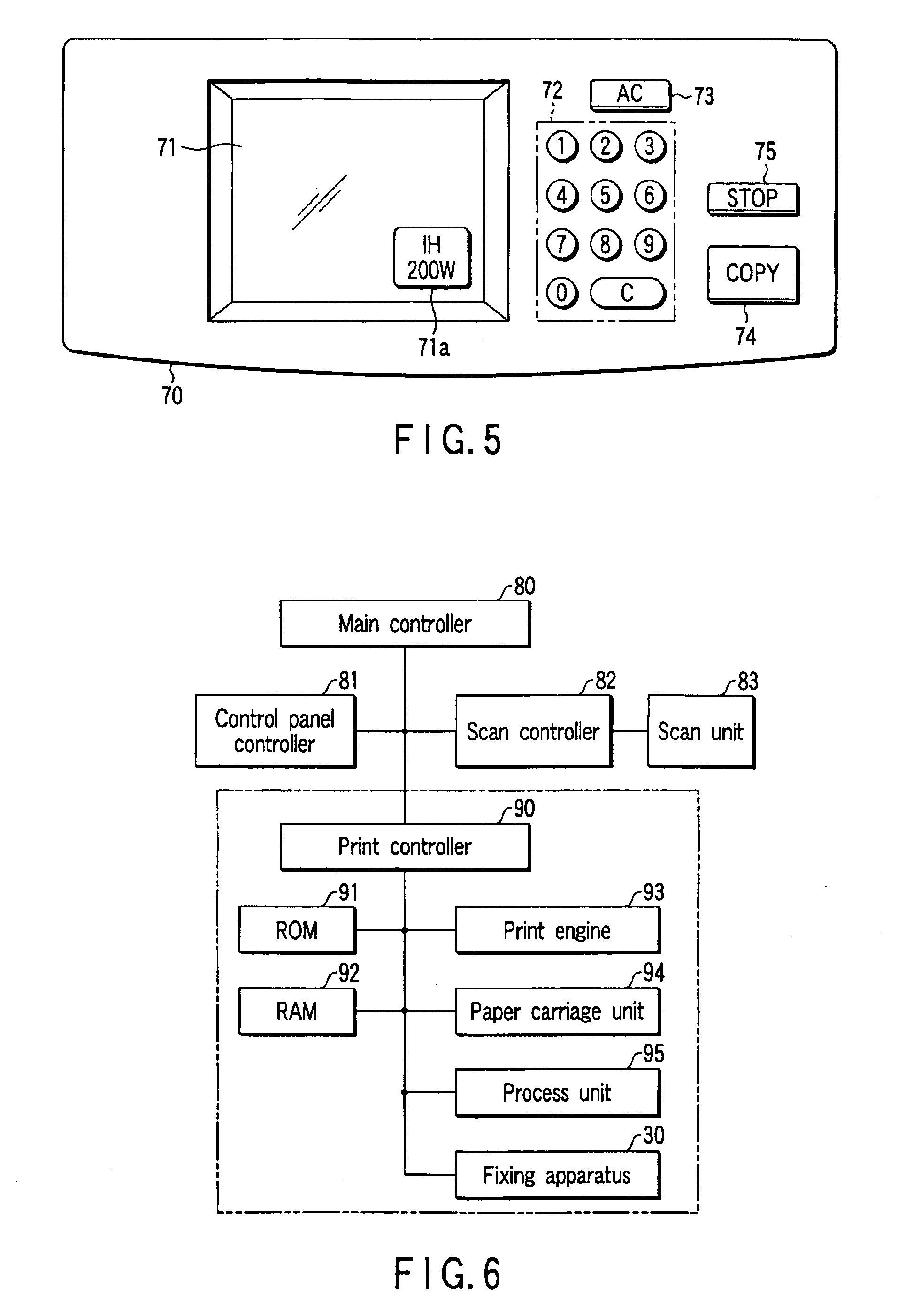
An image forming apparatus according to the present invention includes a scan unit (scan unit 83 described later) that optically reads an image of a document, a process unit (process unit 95 described later) that forms a developer image corresponding to the image read by the scan unit on image forming paper-sheet, and a fixing device (fixing device 30 described later) that fixes the developer image on the paper-sheet by heating. Since the configuration of the image forming apparatus is described specifically in previously filed U.S. patent application Ser. No. 09 / 955,089, its descriptions are omitted.

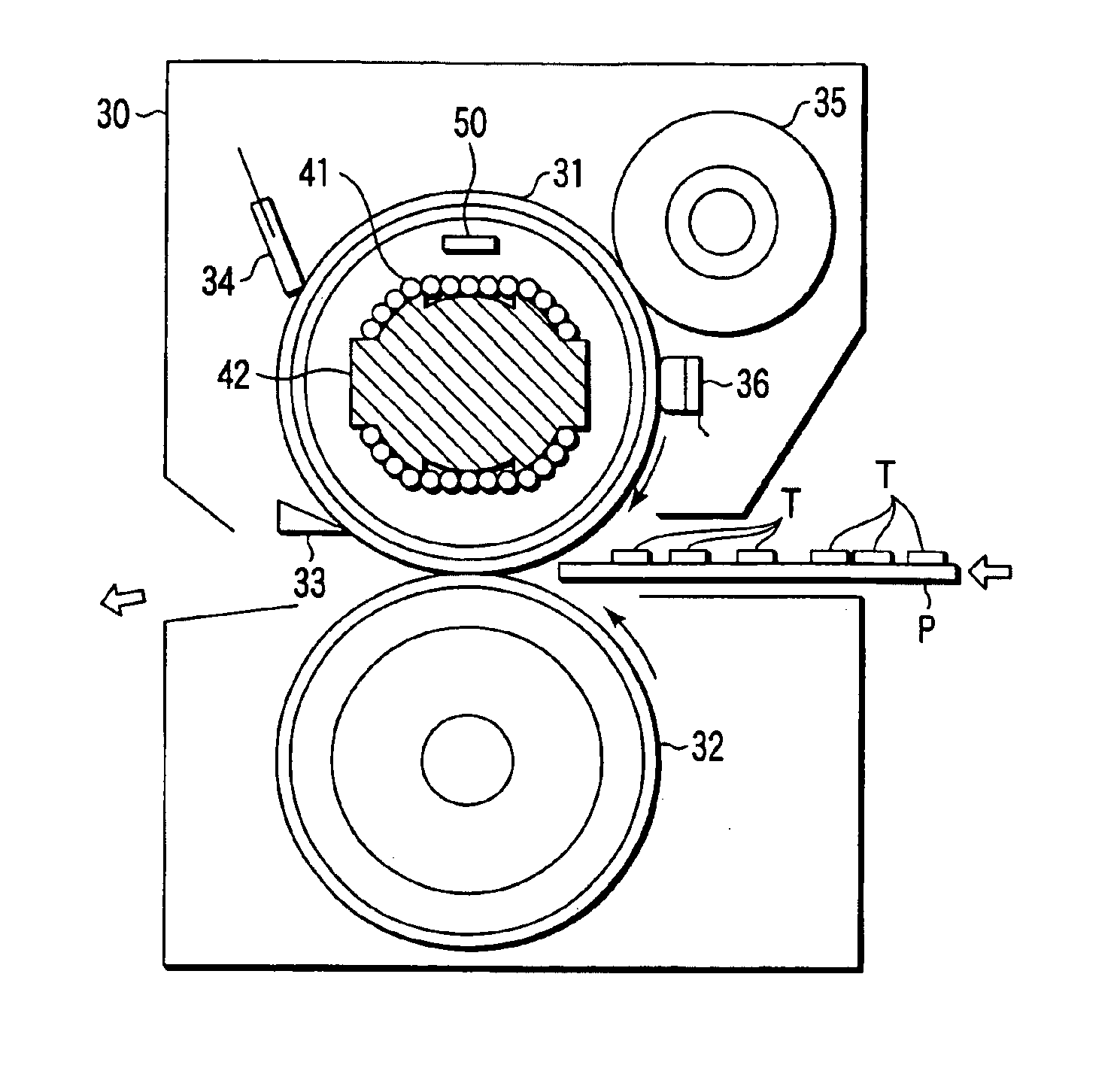
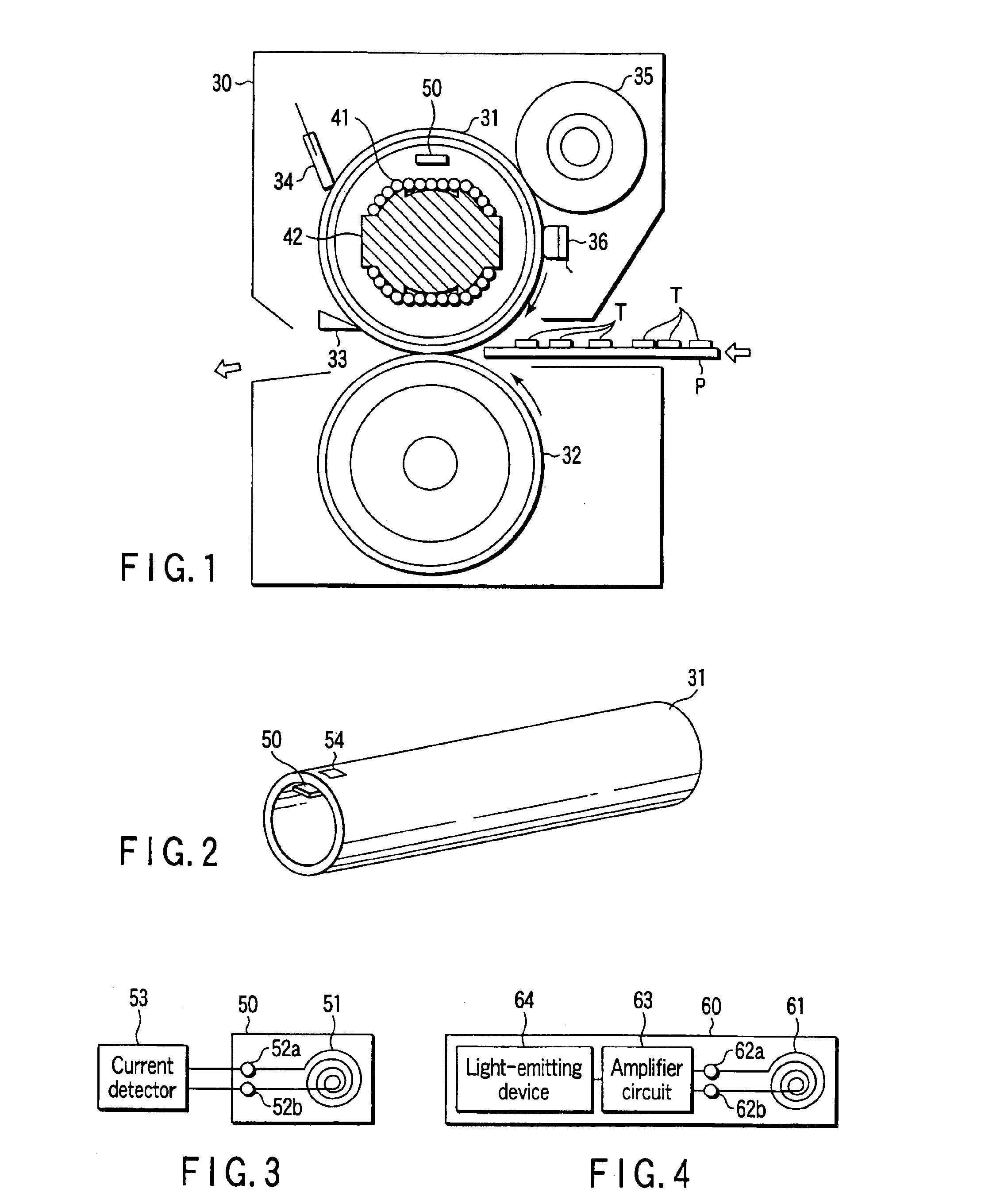
FIG. 1 shows a configuration of the fixing apparatus 30.

The fixing apparatus 30 includes a heating member, e.g., a heating roller 31. The heating roller 31 and pressure roller 32 are vertically arranged so as to catch a carrying path of image forming paper-sheet P therebetween. The pressure rolle...

second embodiment

[2] the present invention will now be described.

As shown in FIG. 12, coils 41 are provided outside a heating roller 31. The coils 41 are mounted on a core 44 and the core 44 is held by a holding member 45. The holding member 45 always maintains a fixed distance between each of the coils 41 and the heating roller 31.

The holding member 45 is provided with an oil coating member 46, and the oil coating member 46 slides on the outer surface of the heating roller 31. The oil coating member 46 is made of felt and contains oil. The oil is applied to the outer surface of the heating roller 31. The oil coating member 46 has a grip 46a. If an operator holds and pulls the grip 46a, he or she can remove the coating member 46 from the holding member 45 and replace it with another one.

The oil coating member 46 is adopted in place of the oil coating roller 35 of the first embodiment.

Since the coils 41 are provided outside the heating roller 31 as described above, the heating roller 31 can be decrea...

third embodiment

[3] the present invention will now be described.

As shown in FIG. 13, coils 41 are provided outside a heating roller 31. The coils 41 are mounted on a core 44 and the core 44 is held by a holding member 45.

The holding member 45 is provided with a cleaning member 47 and the cleaning member 47 slides on the outer surface of the heating roller 31. The cleaning member 47 is made of felt and used to remove a developer and dust from the outer surface of the heating roller 31. The cleaning member 47 has a grip 47a. If an operator holds and pulls the grip 47a, he or she can remove the cleaning member 47 from the holding member 45 and replace it with another one.

The cleaning member 47 is adopted in place of the cleaning member 34 of the first and second embodiments.

Since the coils 41 are provided outside the heating roller 31 as described above, the heating roller 31 can be decreased in size.

The other configurations, operations and advantages are the same as those of the first embodiment.


PUM


Abstract

A DC circuit 110 is provided to convert the voltage of a commercial AC power supply 100 into a DC voltage having a fixed level and output the DC voltage irrespective of the level of the voltage. The rectifier circuit 110 includes contacts 117, 118 and 119 and functions as one of a full-wave doubler voltage rectifier circuit and a full-wave rectifier circuit according to the opening and closing of each of the contacts.

Description

BACKGROUND OF THE INVENTIONAn image forming apparatus reads an image from a document, forms a developer image corresponding to the read image on paper and fixes the developer image on the paper using a fixing apparatus.The fixing apparatus includes a heating roller and a pressure roller. The fixing apparatus catches the paper-sheet between the heating and pressure rollers and carries it to fix the developer image on the paper-sheet.An induction heating type fixing apparatus contains a coil inside a heating roller. The coil is supplied with a high-frequency current and generates a high-frequency magnetic field. The high-frequency magnetic field causes an eddy current to be generated on the heating roller. Due to Joule heat based on the eddy current, the heating roller generates heat by itself.The high-frequency current is generated from a high-frequency generation circuit (which is also called a switching circuit) that is connected to a commercial AC power supply via a rectifier circ...

Claims


Application Information

Patent Timeline
Patent Type & Authority Patents(United States)
IPC IPC(8): G03G15/20
CPCG03G15/2064
Inventor KINOUCHI, SATOSHITAKAGI, OSAMU
Owner KK TOSHIBA
Why Eureka
Try Eureka