Drive unit for dish washing machines

a technology for driving units and washing machines, applied in the field of dish washing machines, can solve the problems of increasing the time required for the pump housing is not supported by the sump, and the conventional dish washing machine, so as to reduce the number of fixing members, simplify the fixing operation of the motor and the impeller, and simplify the assembly of the drive unit

Active Publication Date: 2010-01-05
LG ELECTRONICS INC
View PDF7 Cites 0 Cited by
  • Summary
  • Abstract
  • Description
  • Claims
  • Application Information

AI Technical Summary

Benefits of technology

[0030]An object of the present invention is to provide a drive unit for dish washing machines wherein the fixing operation of a motor and an impeller is simplified.
[0031]Another object of the present invention is to provide a drive unit for dish washing machines wherein assembly of the drive unit is simplified, and the number of fixing members is considerably reduced.
[0032]Another object of the present invention is to provide a drive unit for dish washing machines that is capable of preventing gaps from being created between components of the drive unit. Another object of the present invention is to provide a drive unit for dish washing machines that is capable of improving pumping performance of the dish washing machine, and reducing the size and the manufacturing costs of the dish washing machine.
[0033]A further object of the present invention is to provide a drive unit for dish washing machines that is capable of improving filtering capacity of the dish washing machine and facilitating discharge of solid waste when a draining operation is performed.

Problems solved by technology

However, the conventional dish washing machine has the following problems.
First, the pump housing is not supported by the sump.
As a result, the fixing operation of the impeller to the shaft of the washing motor is very complicated, and therefore, time required to assemble the drive unit is increased.
As a result, the assembly of the drive unit is very complicated, and the number of fixing members is considerably increased.
As a result, gaps are created between the pump housing and the filter housing and between the filter housing and the cover if the assembly of the pump housing and the filter housing and / or the assembly of the filter housing and the cover is not secure.
Consequently, wash water leaks from the gaps created between the pump housing and the filter housing and between the filter housing and the cover, and therefore, wash water pumping performance is decreased.
Consequently, the size of the dish washing machine is increased, and therefore, the manufacturing costs of the dish washing machine are also increased.
Fourthly, the installation space for the solid waste chamber is seriously restricted due to the various flow channels of the filter housing.

Method used


Image

  • Drive unit for dish washing machines
  • Drive unit for dish washing machines
  • Drive unit for dish washing machines

Examples


Embodiment Construction

[0054]The present invention is further described in the detailed description which follows, by reference to the noted plurality of drawings by way of non-limiting examples of preferred embodiments of the present invention, in which like reference numerals represent similar parts throughout the several views of the drawings, and wherein:

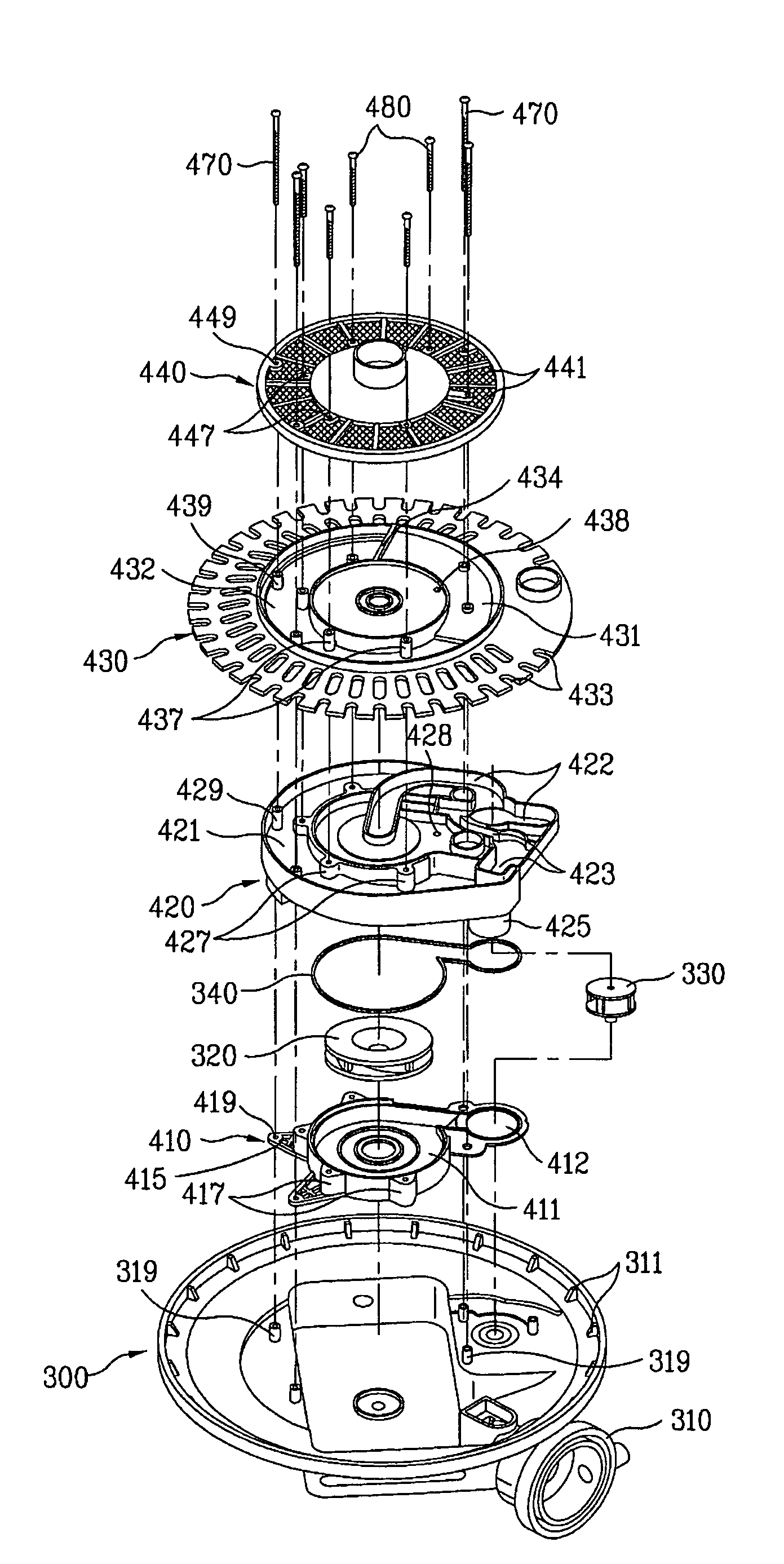
[0055]FIG. 6 is an exploded perspective view illustrating a drive unit for dish washing machines according to a first preferred embodiment of the present invention. As shown in FIG. 6, the drive unit comprises: a sump 100 for receiving wash water; a pump housing 210 disposed inside the sump 100 such that the pump housing 210 is supported by the sump 100, the pump housing 210 having a washing impeller 120 located therein; a flow channel housing 220 disposed to cover the top of the pump housing 210, the flow channel housing 220 having flow channels 222 for guiding some of the wash water pumped out from the washing impeller 120 to washing arms and a soli...


PUM


Abstract

A drive unit for dish washing machines includes a flow channel housing, a filter housing and an arm holder, which are thermally fused to one another to form an integral unit. Consequently, assembly of the drive unit is simplified, leakage of wash water is prevented, and pumping performance is increased. Also, the flow channel housing, the filter housing and the arm holder are concurrently fixed to a pump housing of the drive unit by fixing members. Consequently, the assembly process of the drive unit is simplified, and the coupling force between the components of the drive unit is increased.

Description

[0001]The present disclosure relates to subject matter contained in priority Korean Application No. 2005-0002811, filed on Jan. 12, 2005, the disclosure of which is herein expressly incorporated by reference in its entirety.BACKGROUND OF THE INVENTION[0002]1. Field of the Invention[0003]The present invention relates to a dish washing machine, and more particularly, to a drive unit for dish washing machines that can be easily assembled and is capable of improving wash water filtering performance.[0004]2. Discussion of the Related Art[0005]Generally, a dish washing machine is a machine that injects wash water to dishes to wash the dishes, and heats the washed dishes to dry the washed dishes. A conventional dish washing machine is illustrated in FIG. 1. The construction of the conventional dish washing machine will be described hereinafter with reference to FIG. 1.[0006]As illustrated in FIG. 1, the conventional dish washing machine comprises: upper and lower injection arms 4 and 5; up...

Claims


Application Information

Patent Timeline
Patent Type & Authority Patents(United States)
IPC IPC(8): A47L15/23
CPCA47L15/4204A47L15/4208A47L15/4225C02F11/12F26B3/22F26B2200/18
Inventor JEON, SI MOONLEE, TAE HEEPARK, YOUNG HWAN
Owner LG ELECTRONICS INC
Why Eureka
Try Eureka