Developer container and image forming device equipped with same

a technology of image forming device and development container, which is applied in the direction of instruments, electrographic process apparatus, optics, etc., can solve the problems of imposing restrictions on shape and siz

Active Publication Date: 2019-03-19
KYOCERA DOCUMENT SOLUTIONS INC
View PDF11 Cites 0 Cited by
  • Summary
  • Abstract
  • Description
  • Claims
  • Application Information

AI Technical Summary

Benefits of technology

[0004]It is an object of the present invention to provide a developer storage container configured to inhibit a situation where an input gear unit engageable with a stirring member restricts a lid fixing operation, and an image forming apparatus equipped with the developer storage container.
[0007]The present invention can provide a developer storage container configured to inhibit the situation where the input gear unit engageable with the stirring member restricts a lid fixing operation, and an image forming apparatus equipped with the developer storage container.

Problems solved by technology

In this case, there is a problem that a measure for preventing the input gear unit from hindering the lid welding operation imposes restrictions on a shape and a size of the input gear unit.

Method used


Image

  • Developer container and image forming device equipped with same
  • Developer container and image forming device equipped with same
  • Developer container and image forming device equipped with same

Examples


Embodiment Construction

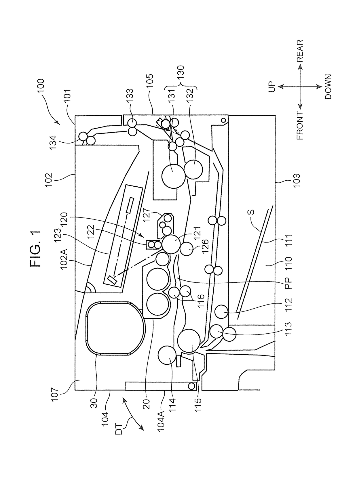
[0021]With reference to the drawings, the present invention will be described based on one embodiment thereof. FIG. 1 is a sectional view schematically showing an internal structure of a printer 100 (image forming apparatus) according to one embodiment of the present invention. The printer 100 shown in FIG. 1 is a so-called monochrome printing machine. However, in another embodiment, the image forming apparatus may be a color printer, a facsimile machine, a complex machine having functions thereof, or any other type of apparatus for forming a toner image on a sheet. Further, the term used in the following description to express a direction, such as “up (upward)”, “down (downward)”, “front (forward)”, “rear (rearward)”, “left (leftward)” or “right (rightward)”, is merely intended to make descriptions clear, but not meant to limit the principle of the image forming apparatus.

[0022]The printer 100 includes a printer body 101 which houses various devices for forming an image on a sheet ...


PUM


Abstract

A developer storage container (30) includes: a container body (31); a lid (32); a stirring member (34); and an input gear (36). The container body includes: a bottom portion (310); an opening (31P) extending in a longitudinal direction thereof; a first sidewall (31R) and a second sidewall (31L); and a storage space (30S) for storing developer therein. The second sidewall includes a bearing portion (312) disposed to face the storage space. The first sidewall includes: a shaft hole (313S) communicating between an outside of the container body and the storage space; and a support portion (313T) supporting a distal end of a coupling (342) of the stirring member from therebelow to prevent the stirring member from falling onto the bottom portion, in a state in which a distal pivot portion (341) of the stirring member is inserted into the bearing portion, and the coupling is disposed facing the shaft hole.

Description

TECHNICAL FIELD[0001]The present invention relates to a developer storage container for storing developer thereinside, and an image forming apparatus equipped with the developer storage container.BACKGROUND ART[0002]Heretofore, as a developer storage container for storing developer thereinside, there has been known a toner container as described in JP 2010-96827A. This toner container includes a container body having a toner discharge port opened therein, a lid, a stirring paddle, and a conveyance screw. The lid is welded to an upper end of the container body to thereby form a storage space for toner therein. The stirring paddle is rotated to stir toner in the storage space. Concurrently, the conveyance screw is rotated to convey toner toward the toner discharge port.SUMMARY OF INVENTION[0003]In the toner container described in Patent Literature 1, before welding the lid to the container body, an input gear unit for transferring a rotational drive force to the stirring paddle is cou...

Claims


Application Information

Patent Timeline
Patent Type & Authority Patents(United States)
IPC IPC(8): G03G15/08G03G21/16
CPCG03G15/0889G03G15/08G03G15/0881G03G21/16G03G15/0875G03G2215/085
Inventor ETO, DAISUKE
Owner KYOCERA DOCUMENT SOLUTIONS INC
Why Eureka
Try Eureka