

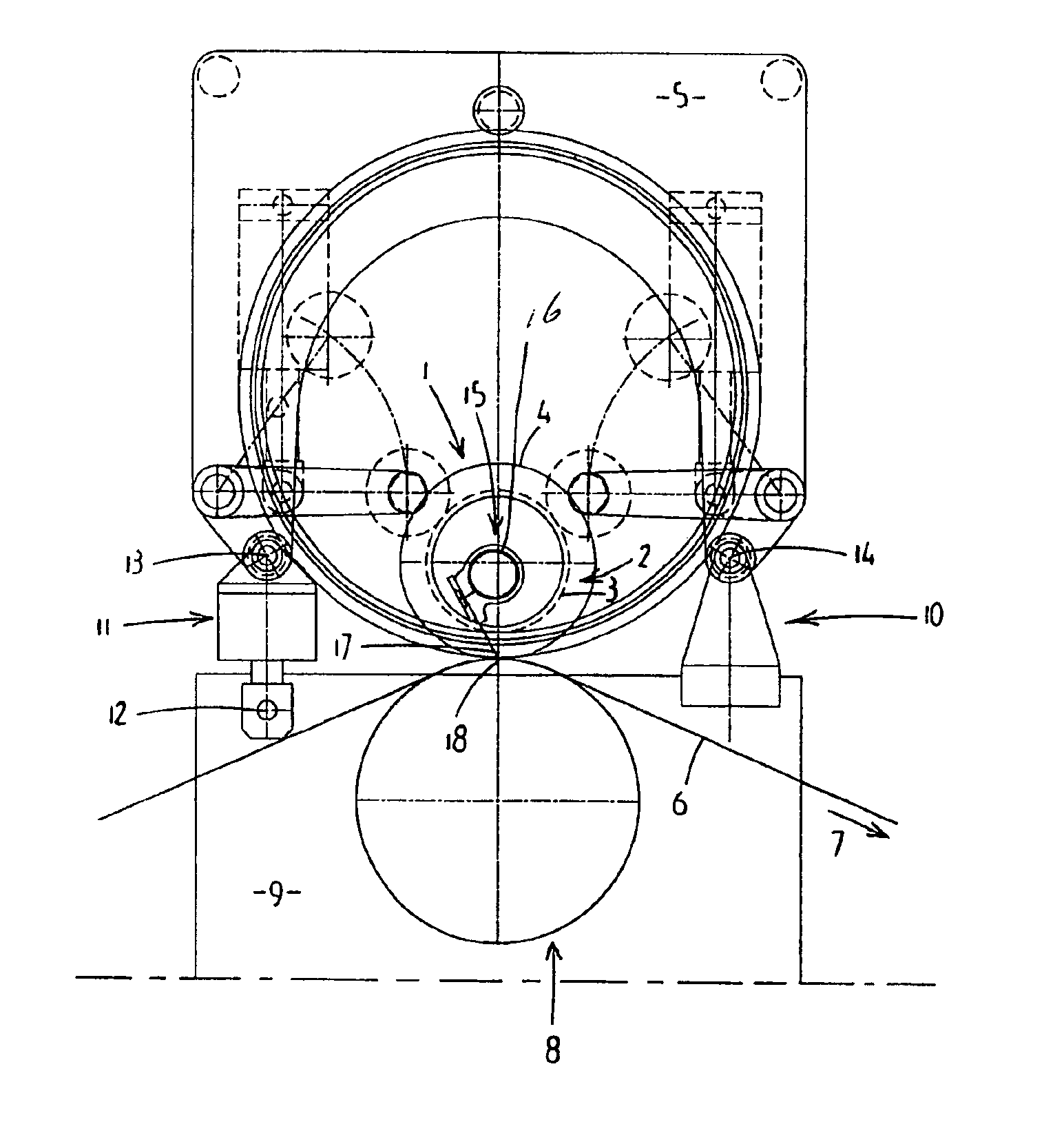
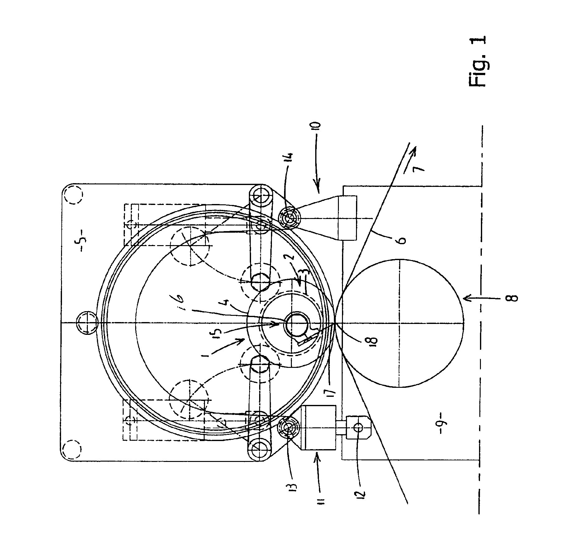
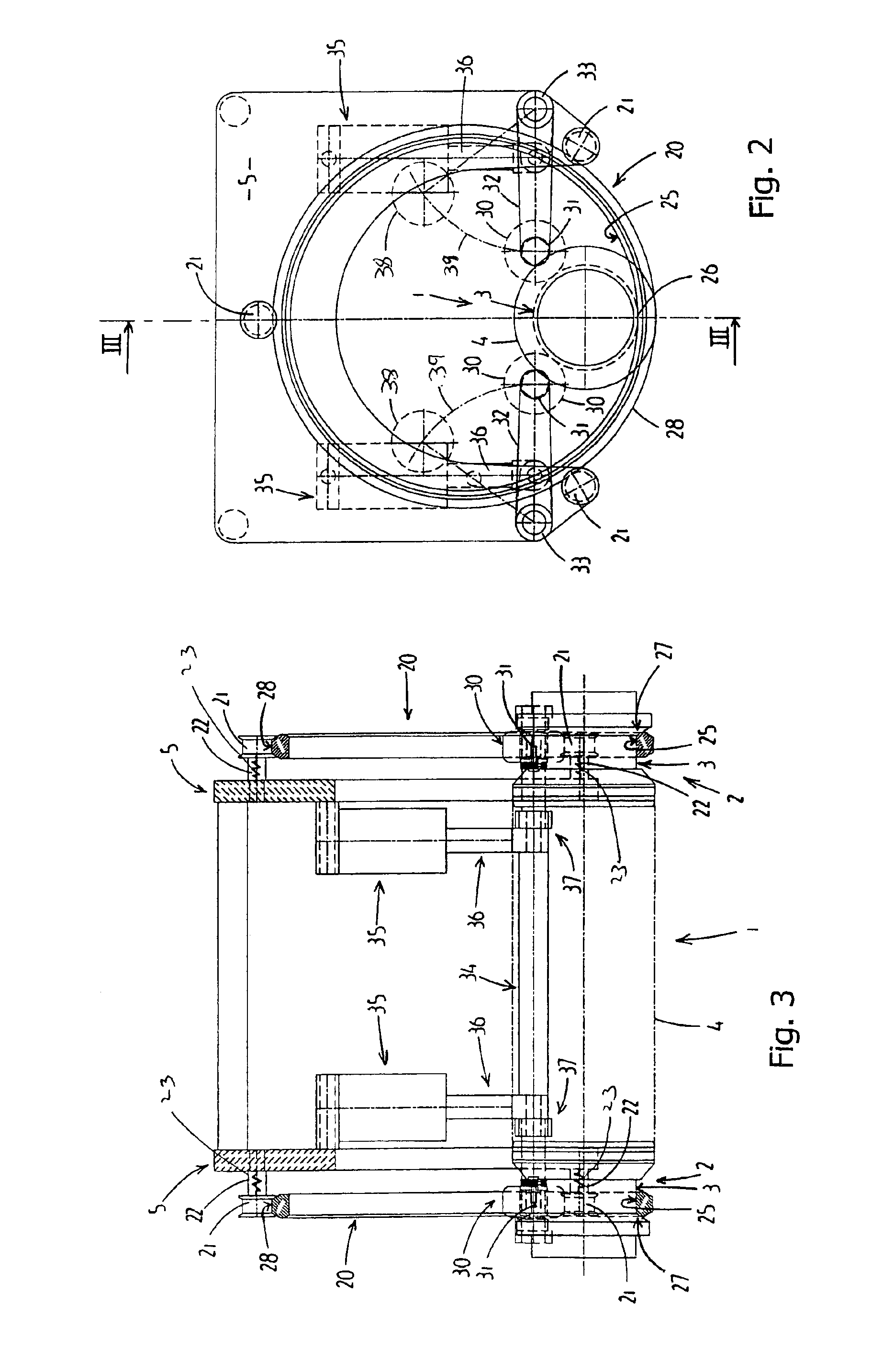
Printing cylinder support unit with support ring
a technology of support unit and printing cylinder, which is applied in the direction of office printing, rotary letterpress machines, coatings, etc., can solve the problems of known support unit, significant drawback of known printing cylinder support unit, and serious restriction of point, so as to achieve easy exchange, less space, and little space
- Summary
- Abstract
- Description
- Claims
- Application Information
AI Technical Summary
Benefits of technology
Problems solved by technology
Method used
Image

Examples
second embodiment
A second embodiment is shown in FIGS. 4 and 5, in which identical reference numerals denote the same components as in the first preferred embodiment. Unlike in the above embodiment, the support ring 20 is secured rotatably to the support frame 5 via an annular bearing 40. This annular bearing 40 is shown in more detail in FIG. 6, which shows an outer race 41 and an inner race 42, which can move with respect to one another on account of balls 43. A plastic annular component, which together with the inner race 42 forms the support ring 20 with running surfaces 25 and 27, is fixedly connected to the inner race 42. The outer race 41 of the annular bearing is connected to the support frame by means of three connecting pieces 52.
In all the drawings, it can be seen that the height of the support ring, which in the first preferred embodiment is the difference between the inner running surface 25 and the outer running surface 28 and in the second preferred embodiment is the difference betwee...
PUM
 Abstract
Description
Claims
Application Information