Automobile vehicle including associated body parts with reduced clearance

Inactive Publication Date: 2005-03-22
FAURECIA BLOC AVANT
View PDF30 Cites 12 Cited by
  • Summary
  • Abstract
  • Description
  • Claims
  • Application Information

AI Technical Summary

Benefits of technology

The abutment advantageously projects from a bottom face of the hood.
The abutment is advantageously at a front edge of the hood.
The body component is advantageously a wing of the vehicle.

Problems solved by technology

This can cause imperfect relative positioning of the components and lead to less than

Method used


Image

  • Automobile vehicle including associated body parts with reduced clearance
  • Automobile vehicle including associated body parts with reduced clearance
  • Automobile vehicle including associated body parts with reduced clearance

Examples


Embodiment Construction

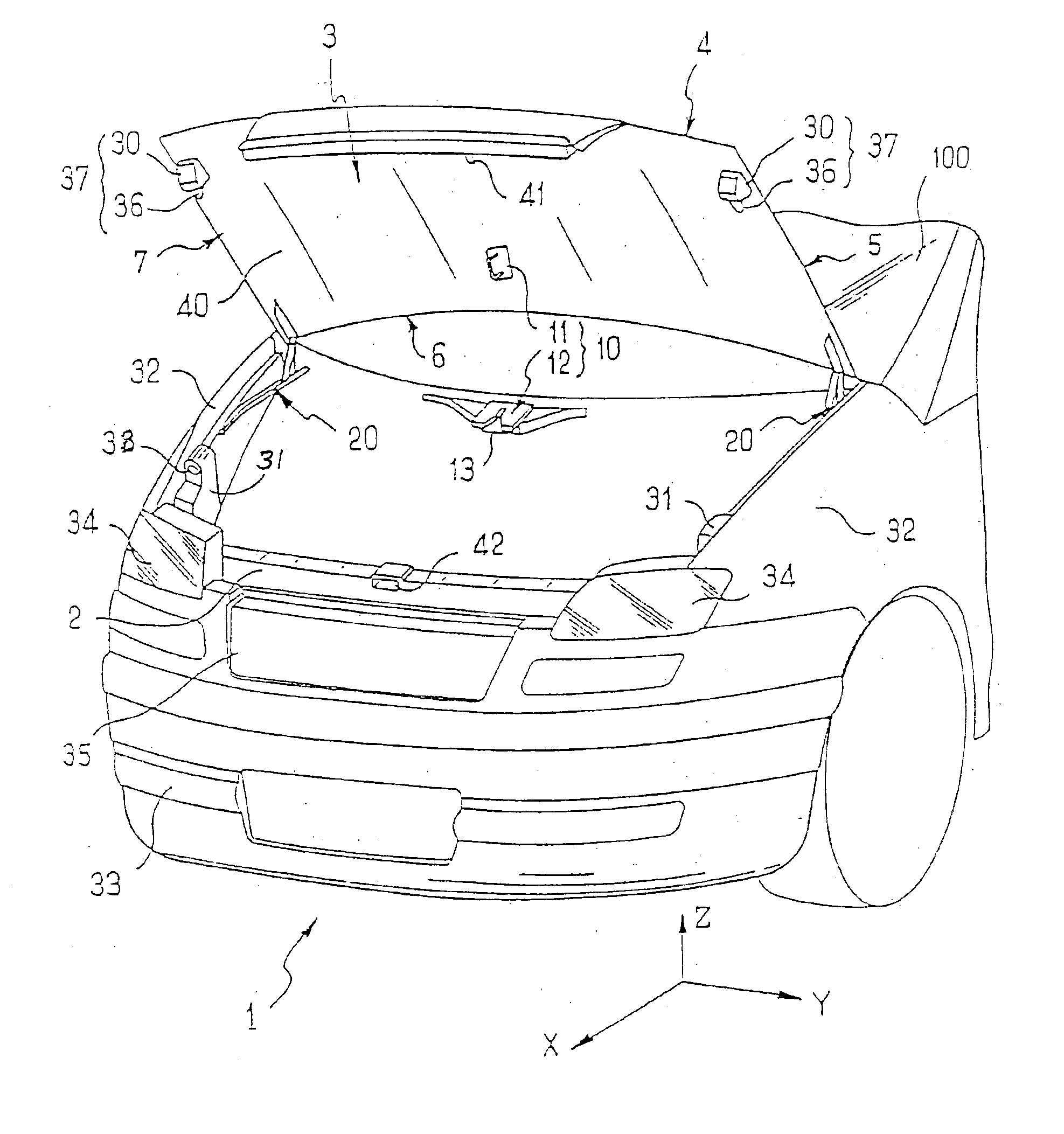
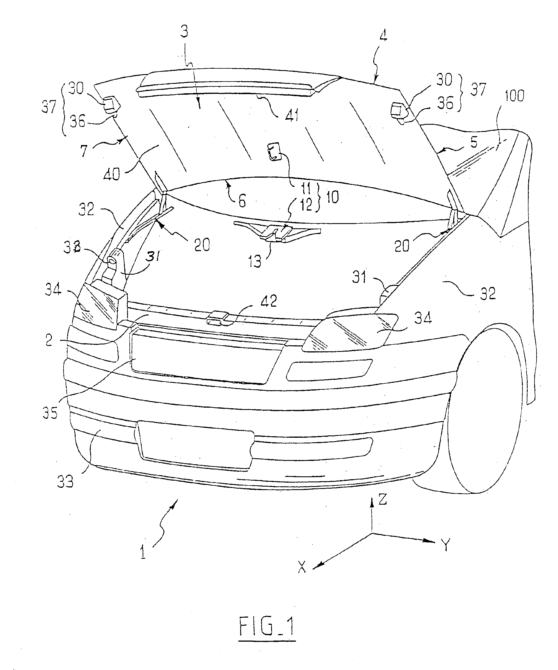
Throughout the following description, the axes X, Y and Z are as shown in FIG. 1: the axis X is horizontal and in the direction of movement of the vehicle, the axis Y is horizontal and perpendicular to the axis X, and the axis Z is directed upward and perpendicular to the axes X and Y. The axes therefore form a direct frame of reference.

Referring to FIG. 1, the front body 1 of a vehicle in accordance with the present invention includes a scuttle 33, a grille 35, two wings 32, two light units 34 at the front ends of the wings 32 and on respective opposite sides of the grille 35, and a hood 3, the bodyshell as a whole covering a chassis, of which only a portion 2 is shown.

The hood 3 includes a wall 40 delimited by a more or less convex front edge 4, a more or less straight right-hand edge 5, a more or less concave rear edge 6 and a more or less straight left-hand edge 7.

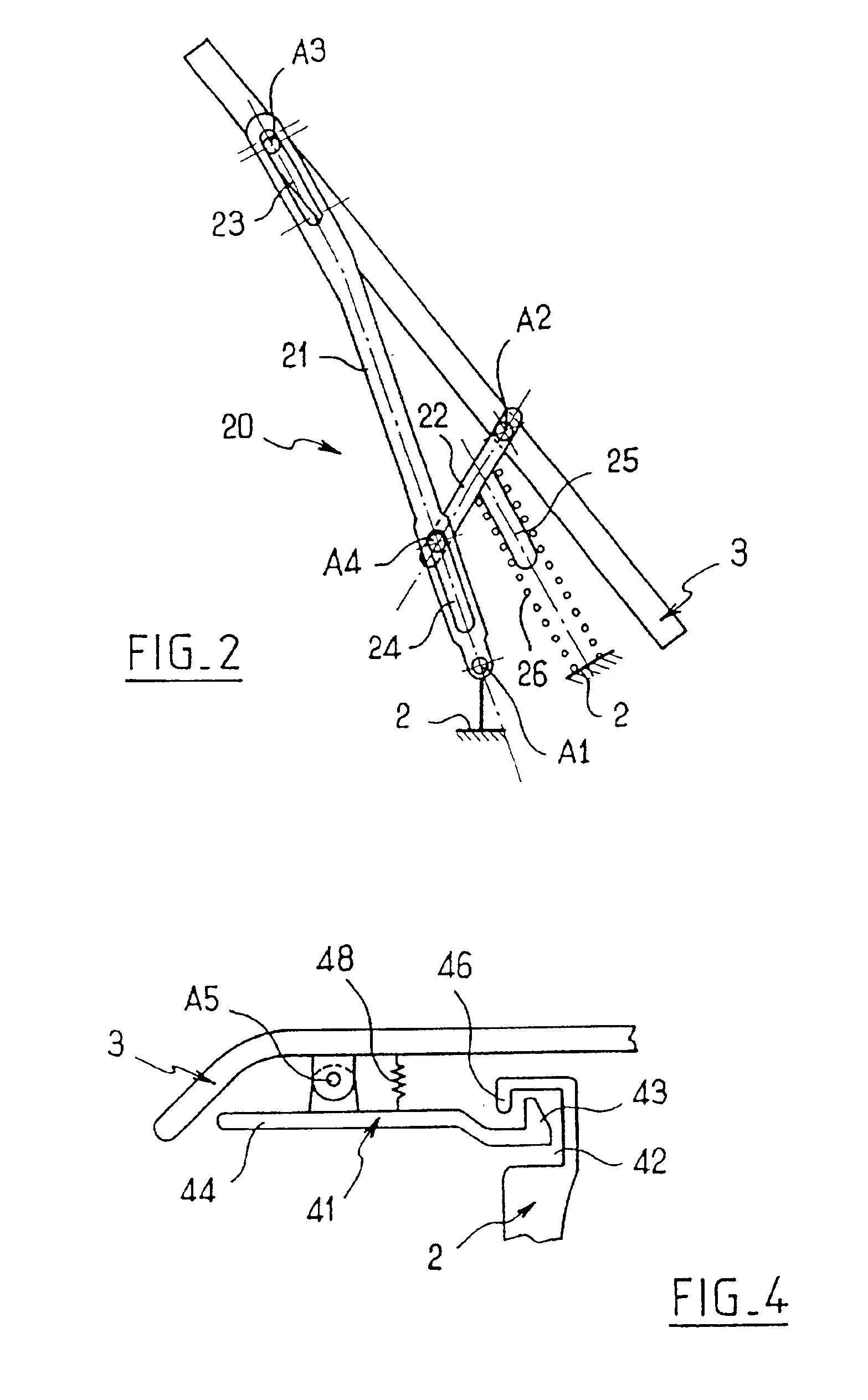
The hood 3 includes connecting devices 20 which connect it to the chassis of the vehicle and enable it to move relat...


PUM


Abstract

A vehicle includes a chassis, a hood mobile relative to the chassis and at least one body component. Contact of the body component with the hood determines a position of the body component relative to the hood.

Description

BACKGROUND OF THE INVENTION1. Field of the InventionThe invention relates to systems for assembling vehicle body components.2. Description of the Prior ArtThere exist vehicles with body components fixed independently to the structure of the vehicle, such as wings, bumpers and a radiator grille. The hood, another body component, pivots relative to the structure of the vehicle on hinges at the rear of the hood, i.e. at the end adjoining the windshield frame. Each component is referenced relative to the chassis. It follows that the string of dimensions for positioning the various body components relative to each other passes through the structure of the vehicle. The string of dimensions of this type of component assembly therefore makes large clearances obligatory. This can cause imperfect relative positioning of the components and lead to less than graceful alignments and flush relationships, compromising the esthetics of the vehicle.An object of the present invention is to minimize t...

Claims


Application Information

Patent Timeline
IPC IPC(8): B62D25/12B62D25/10E05D3/00E05D3/06E05D15/40
CPCB62D25/12E05D3/18E05Y2900/536E05D15/406
Inventor BROGLY, SEBASTIENGEORGE, GHISLAIN
Owner FAURECIA BLOC AVANT
Why Eureka
Try Eureka