Apparatus and method for controlling an electrical switch array

a technology of electrical switch array and actuator, which is applied in the direction of static indicating device, coding, instruments, etc., can solve the problems of excess current flow, current drain, and excessive current flow

Inactive Publication Date: 2005-03-22
TEXAS INSTR INC
View PDF8 Cites 2 Cited by
  • Summary
  • Abstract
  • Description
  • Claims
  • Application Information

AI Technical Summary

Benefits of technology

An electrical switching apparatus configured for low power operation includes: (a) a plurality of switching devices arranged in a switching array permitting sensing of individual switching events by selected switching devices; (b) a switching control device coupled with the switching array that provides power to the switching array for sensing and for a first time interval after a first switching device is actuated. The control device identifies the first switching device during the first time interval and interrupts power to the switching array after the first time interval until the first switching device is deactuated. The control device provides power to the switching array for a second time interval after the first switching device is deactuated. The control device determines during the second time interval whether a second switching device other than the first switching device is actuated.

Problems solved by technology

Often during use of such products a condition occurs where one or more keys is stuck or otherwise held in an actuated position.
For example, a wireless phone in the bottom of a user's purse or in a user's pocket may have one or more of the keys in its keypad array inadvertently pressed and held down (i.e., in an actuated position) for a long period of time.
Depending upon the circuit design and implementation of the keypad interface such a holding down of a keyswitch can draw power and cause excess current to flow.
Excess current flow can prematurely drain the batteries in battery-operated products such as wireless phones, PDA devices and similar products.
The problem with such prior art solutions is that the required periodic “awakening” and the repeated polling consume a certain amount of power and therefore cause current drain that shortens battery life.

Method used


Image

  • Apparatus and method for controlling an electrical switch array
  • Apparatus and method for controlling an electrical switch array
  • Apparatus and method for controlling an electrical switch array

Examples


Embodiment Construction

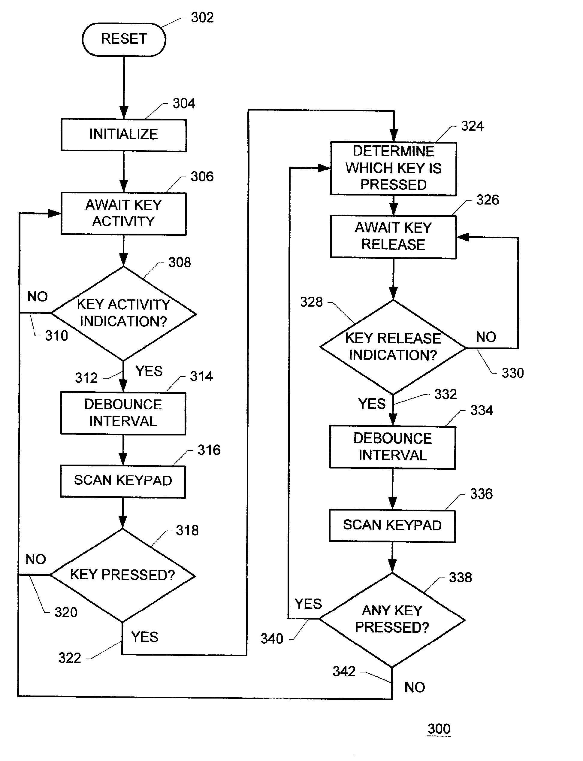
The preferred embodiment of the apparatus of the present invention employs a microprocessor device that responds to rising and falling edges of signals. In the illustrative descriptions presented herein the apparatus is described as having a first response to a rising signal edge and a second response to a falling signal edge. Those skilled in the art of microprocessor system design will readily recognize that such an implementation is only exemplary and that a microprocessor could as easily be employed to respond with the second response to a rising signal edge and the first response to a falling signal edge.

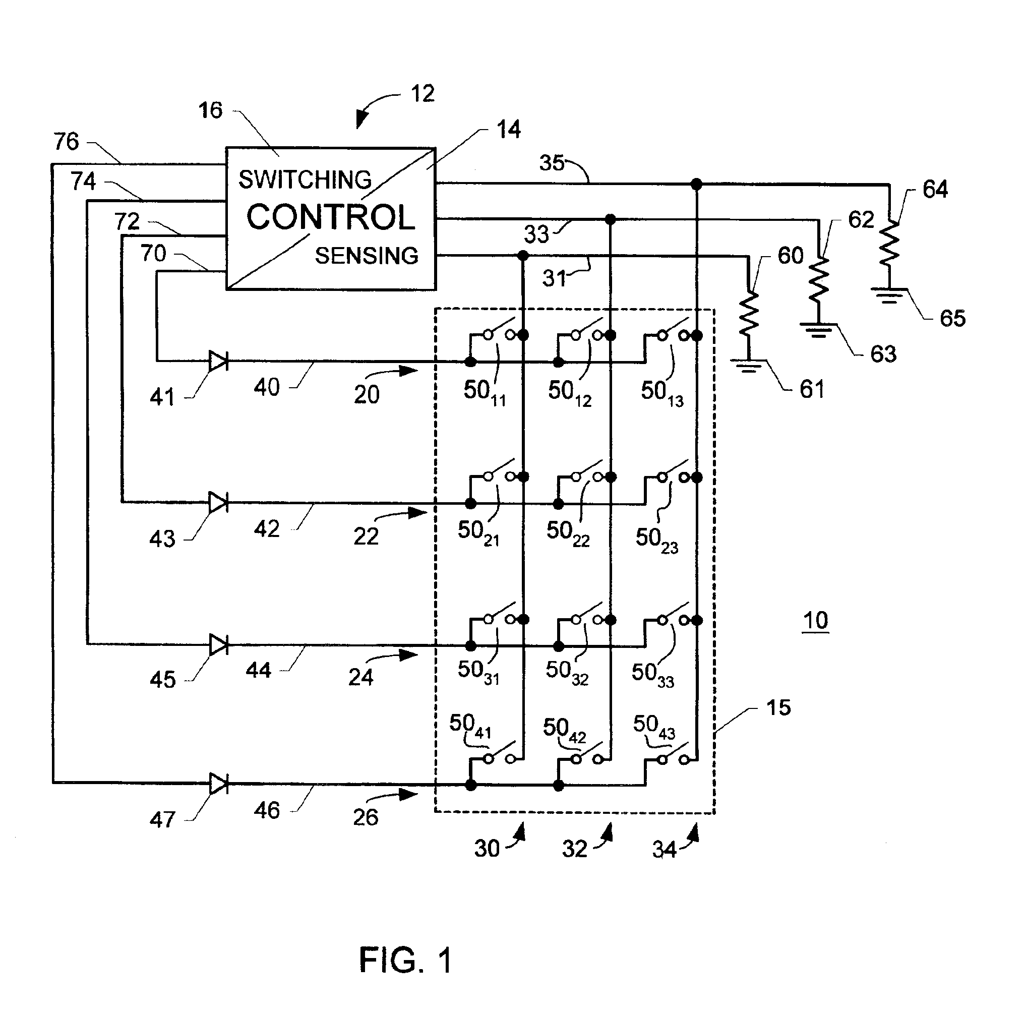
FIG. 1 is a schematic diagram illustrating the preferred embodiment of the present invention employed with an exemplary keyswitch array. In FIG. 1, a system 10 includes a control unit 12 and an electrical switch array 15. Electrical switch array 15 is arranged in a plurality of rows n, such as rows 20, 22, 24, 26 and a plurality of columns m, such as columns 30, 32, 34. A plura...


PUM


Abstract

An electrical switching apparatus configured for low power operation includes: (a) a plurality of switching devices arranged in a switching array permitting sensing of individual switching events by selected switching devices; (b) a switching control device coupled with the switching array that provides power to the switching array for sensing and for a first time interval after a first switching device is actuated. The control device identifies the first switching device during the first time interval and interrupts power to the switching array after the first time interval until the first switching device is deactuated. The control device provides power to the switching array for a second time interval after the first switching device is deactuated. The control device determines during the second time interval whether a second switching device other than the first switching device is actuated.

Description

BACKGROUND OF THE INVENTIONThe present invention is directed to electrical switch arrays, and especially to electrical keyswitch arrays, or keypads, of the sort used for portable devices, such as portable telephones, wireless telephones, personal digital assistant (PDA) devices and similar devices.Often during use of such products a condition occurs where one or more keys is stuck or otherwise held in an actuated position. For example, a wireless phone in the bottom of a user's purse or in a user's pocket may have one or more of the keys in its keypad array inadvertently pressed and held down (i.e., in an actuated position) for a long period of time. Depending upon the circuit design and implementation of the keypad interface such a holding down of a keyswitch can draw power and cause excess current to flow. Excess current flow can prematurely drain the batteries in battery-operated products such as wireless phones, PDA devices and similar products.Previous solutions to this problem...

Claims


Application Information

Patent Timeline
Patent Type & Authority Patents(United States)
IPC IPC(8): G06F1/32H03M11/20H03M11/00
CPCG06F1/3203H03M11/20G06F1/3271Y02B60/1257Y02D10/00
Inventor MITCHELL, MICHAEL LANE
Owner TEXAS INSTR INC
Why Eureka
Try Eureka