High resolution and low power magnetometer using magnetoresistive sensors

a magnetoresistive sensor, high-resolution technology, applied in the field of magnetic field sensors, can solve the problems of high cost of individual coils, upset of the sensitivity of the mr sensor, and inability to use large external magnets, etc., to achieve higher resolution sensing and improve the noise level of the sensor

Inactive Publication Date: 2006-06-22
HONEYWELL INT INC
View PDF4 Cites 41 Cited by
  • Summary
  • Abstract
  • Description
  • Claims
  • Application Information

AI Technical Summary

Benefits of technology

[0015] A sensor having a sensing element is described. The sensing element has an associated sensitivity to a signal of interest. An external force may be used during operation of the sensor to modify, adjust, or modulate the sensitivity of the sensor. The modulation

Problems solved by technology

However, the alignment of the domains, and hence the sensitivity of the MR sensor, may be upset after manufacture due to thermal decay and by the presence of powerful magnetic fields near the magnetoresistive material of the MR sensor.
However, large external magnets may not be practical when the MR sensor has already been packaged into a system or when several sensors within a single package must be magnetized in opposite directions.
However, individual coils may be expensive and may be unable to generate the large magnetic fields required to s

Method used


Image

  • High resolution and low power magnetometer using magnetoresistive sensors
  • High resolution and low power magnetometer using magnetoresistive sensors
  • High resolution and low power magnetometer using magnetoresistive sensors

Examples


Embodiment Construction

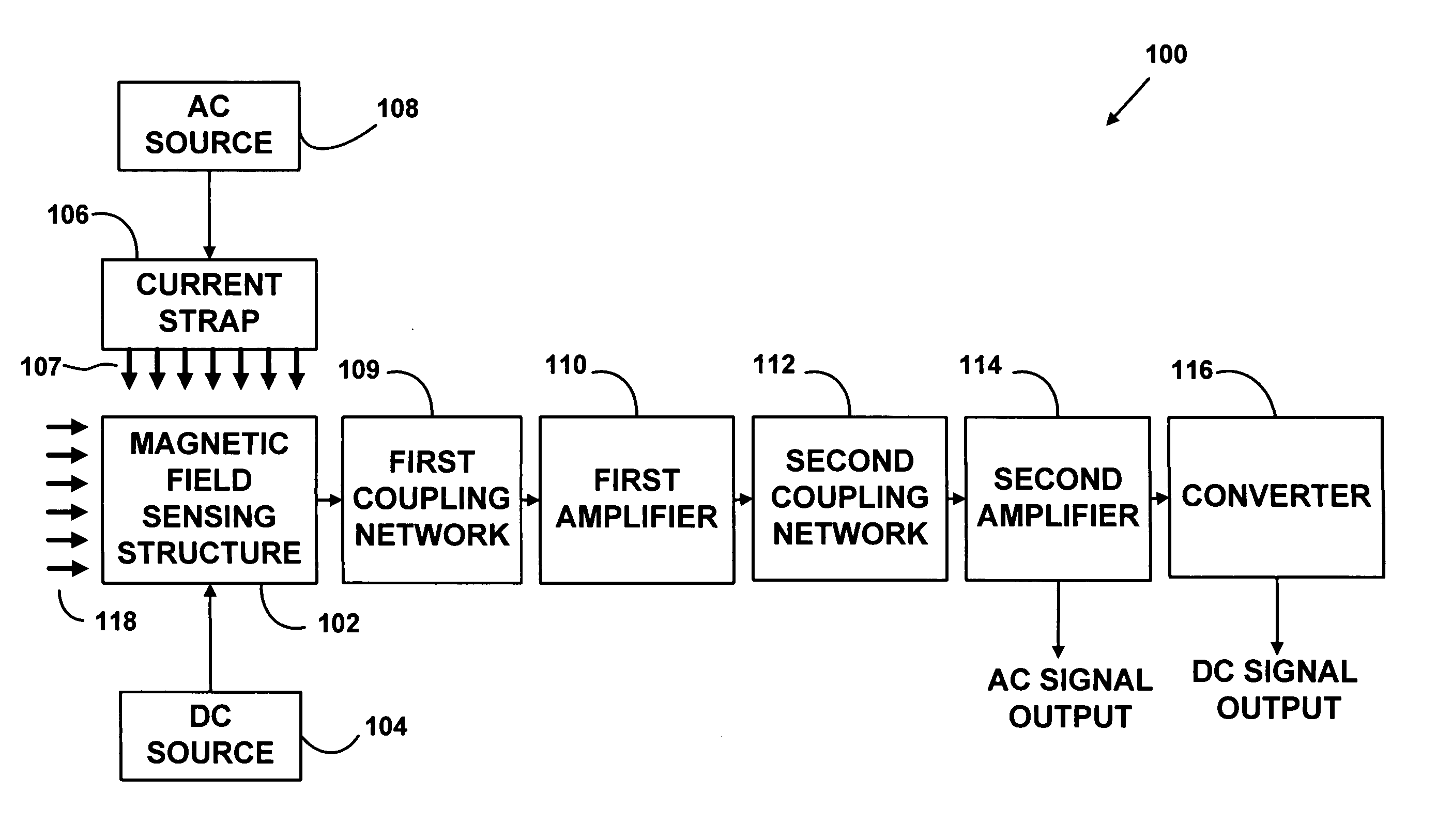
[0031]FIG. 1 is a block diagram of a magnetic field sensor 100. The magnetic field sensor 100 is typically formed on a semiconductor substrate using integrated circuit techniques. However, other substrate materials and fabrication techniques may be used. The magnetic sensor 100 may include a magnetic field sensing structure 102, a direct current (“DC”) source 104, a current strap 106, an alternating current (“AC”) source 108, a first coupling network 109, a first amplifier 110, a second coupling network 112, a second amplifier 114, and a converter 116.

[0032] Alternative components of the magnetic field sensor 100 may also be used instead of what is illustrated in FIG. 1. Also, the magnetic field sensor 100 may not require all components in all configurations. For example, only one coupling network and one amplifier may be used in some configurations of the magnetic field sensor 100.

[0033] The magnetic field sensing structure 102 may operate to detect external magnetic fields. The ...


PUM


Abstract

A magnetometer is disclosed that enables high resolution magnetometry using magnetoresistive sensors that consume less power. The magnetometer exploits the ability of the sensor to alter or modulate sensitivity via external means. This modulation effectively transfers the signal of interest from the noisy DC domain to the AC domain by applying an AC signal to a current strap in a magnetic field sensor. The AC signal causes a first magnetic field to be formed in a direction perpendicular to the current strap. A magnetic field sensing structure in the magnetic field sensor senses the first magnetic field. The magnetic field sensing structure uses the first magnetic field to sense a second magnetic field. The second magnetic field is an external magnetic field that is of interest. An output of the magnetic field sensing structure is an AC signal that is proportional to the second magnetic field. The AC signal may be further amplified and refined employing signal conditioning techniques.

Description

FIELD [0001] The present invention relates generally to magnetic field sensors, and more specifically, relates to magnetoresistive (“MR”) sensors. BACKGROUND [0002] Magnetic field sensors may be used in many applications, such as magnetic compassing, ferrous metal detection, and current sensing. Magnetic field sensors may detect a magnetic field and its variations in many instances, including machine components, the earth's magnetic field, underground minerals, and electrical devices. [0003] One type of a magnetic field sensor is an MR sensor. The MR sensor is typically composed of magnetoresistive material and formed using integrated circuit fabrication techniques. The magnetoresistive material may be permalloy, which is a ferromagnetic alloy containing nickel and iron. [0004] The magnetoresistive material may be arranged in thin strips that are several times longer than they are wide. Each magnetoresistive strip may have a long axis, which may be referred to as an “easy” axis, and...

Claims


Application Information

Patent Timeline
IPC IPC(8): G01R33/02
CPCG01R33/09
Inventor WITHANAWASAM, LAKSHMAN S.
Owner HONEYWELL INT INC
Why Eureka
Try Eureka