Reduced noise valve stack connection

a stack connection and valve technology, applied in the field of relief valves, can solve the problems of shockwave generation accompanied by, extremely high noise level, etc., and achieve the effects of suppressing noise generated, high noise level, and facilitating formation

Active Publication Date: 2005-11-29
CONTROL COMPONENTS INC
View PDF14 Cites 23 Cited by
  • Summary
  • Abstract
  • Description
  • Claims
  • Application Information

AI Technical Summary

Benefits of technology

[0012]The bellows is configured to minimize or eliminate excessive forces and bending moments in the silencer system caused by thermal expansion in the vent stack and in the inner sleeve. Importantly, the muffler disc may be oriented relative to the inner sleeve such that high-pressure fluid exits the inner sleeve and impinges the muffler disc prior to creating shockwaves. If allowed to expand freely when exiting the inner sleeve, the high-pressure fluid may result in the generation of shockwaves accompanied by extremely high noise levels. Advantageously, the silencer system of the present invention is specifically adapted to prevent such shockwaves from forming.
[0014]The muffler disc is oriented above the sleeve outlet of the inner sleeve although the muffler disc may be disposed directly upon (i.e., in direct contact with) the sleeve outlet. The muffler disc may preferably be oriented relative to the sleeve outlet such that the fluid impinges the muffler disc prior to creating shockwaves. The introduction of high-pressure fluid such as steam into the inner sleeve of the silencer system facilitates the formation of an underexpanded flow emanating from the sleeve outlet. The flow may accelerate to supersonic speed upon reaching the relatively lower pressure area of the vent stack surrounding the sleeve outlet.
[0015]If allowed to freely expand, the flow will result in the eventual formation of a shockwave downstream of the sleeve outlet. Akin to the shockwave sometimes visible in the exhaust plume of a military fighter jet engine, such a shockwave emanating from the sleeve outlet may result in the production of extremely high noise levels. The muffler disc of the present invention is specifically configured and oriented above the inner sleeve to prevent such shockwave from forming and to suppress noise generated by other phenomena in a manner which will be described in more detail below.

Problems solved by technology

If allowed to expand freely when exiting the inner sleeve, the high-pressure fluid may result in the generation of shockwaves accompanied by extremely high noise levels.

Method used


Image

  • Reduced noise valve stack connection
  • Reduced noise valve stack connection
  • Reduced noise valve stack connection

Examples


Embodiment Construction

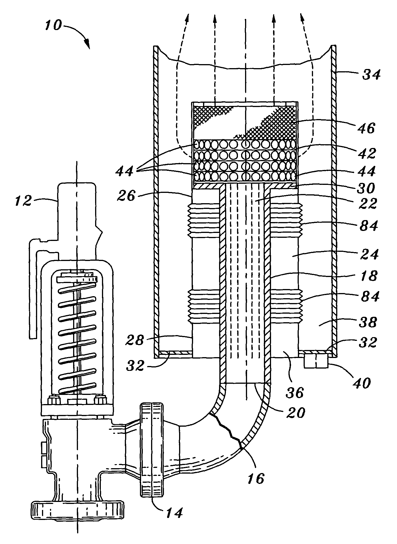
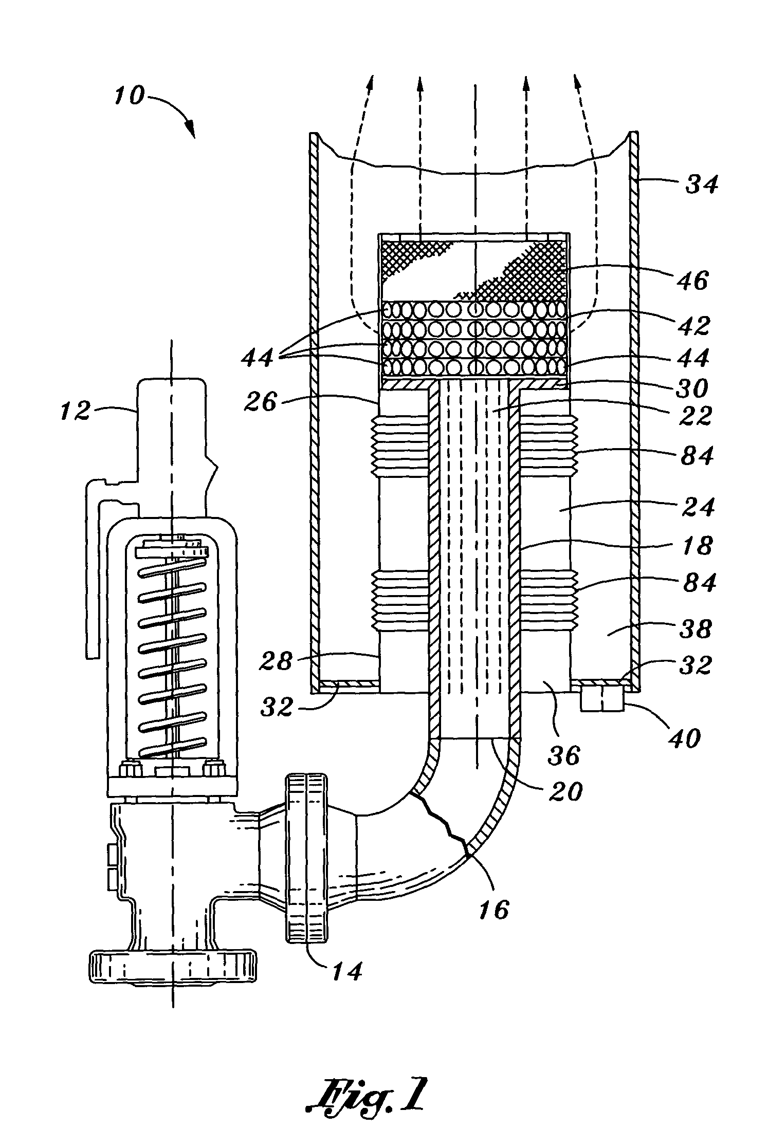
[0022]Referring now to the drawings wherein the showings are for purposes of illustrating preferred embodiments of the present invention only, and not for purposes of limiting the same, FIG. 1 illustrates in cross section a silencer system 10 fluidly connected to a relief valve 12. The silencer system 10 comprises an inner sleeve 18, a flexible bellows 24, a vent stack 34 and a muffler disc 46 disposed above the inner sleeve 18. Importantly, the muffler disc 46 may be oriented relative to the inner sleeve 18 such that high-pressure fluid exits the inner sleeve 18 and impinges the muffler disc 46 prior to creating shockwaves. As will be recognized, the generation of shockwaves may result in the production of extremely high noise levels. The silencer system 10 of the present invention is specifically adapted to prevent such shockwaves from forming, as will be described in greater detail below.

[0023]The inner sleeve 18 may be configured as an elongate, tubular shape which defines a flo...


PUM


Abstract

Disclosed is a silencer system configured to allow for thermal growth thereof while attenuating noise created by expansion of high-pressure fluid flowing therethrough. The silencer system comprises a tubular inner sleeve, a tubular flexible bellows, a tubular vent stack and a muffler disc. The inner sleeve has a sleeve inlet and a sleeve outlet. The inner sleeve is concentrically disposed in spaced relation within the bellows which is concentrically disposed in spaced relation within the vent stack. The bellows is configured to allow for axial and lateral movement of the inner sleeve relative to the vent stack when fluid passes through the silencer system to minimize excessive deflective forces and bending moments on the silencer system. The muffler disc is oriented relative to the sleeve outlet such that the high-pressure fluid impinges the muffler disc prior to creating shockwaves which may otherwise result in the production of high noise levels.

Description

CROSS-REFERENCE TO RELATED APPLICATIONS[0001](Not Applicable)STATEMENT RE: FEDERALLY SPONSORED RESEARCH / DEVELOPMENT[0002](Not Applicable)BACKGROUND OF THE INVENTION[0003]The present invention relates generally to relief valves and, more particularly, to a uniquely configured silencer system which is specifically adapted to accommodate thermal expansion displacements that may occur in piping systems through which high-pressure fluid is vented. The silencer system is configured to facilitate a reduction in unwanted noise created by the flow of the fluid by eliminating noise-generating sources created by the flow.[0004]Vent silencers have been employed in various industries to muffle high velocity air or gas, including steam, which is flowing or venting to the atmosphere. For example, vent silencers are often used in conjunction with pressure relief valves or safety valves of the type utilized in high-pressure, high temperature steam service for relieving over-pressure from steam gener...

Claims


Application Information

Patent Timeline
Patent Type & Authority Patents(United States)
IPC IPC(8): F01N1/08F16K47/02F16L55/033
CPCF01N1/087F01N1/089F16K47/02F16L55/033F16L55/0332
Inventor SCHMAEMAN, DALE E.
Owner CONTROL COMPONENTS INC
Why Eureka
Try Eureka