Centrifugal blower and air conditioner with the same

a centrifugal fan and centrifugal fan technology, which is applied in the direction of positive displacement liquid engines, liquid fuel engine components, fluid engines, etc., can solve the problems of increasing noise level and increasing the quantity of air sucked in from the cooling air hole, so as to achieve suppressing the increase in noise level

Inactive Publication Date: 2005-05-19
DAIKIN IND LTD
View PDF4 Cites 22 Cited by
  • Summary
  • Abstract
  • Description
  • Claims
  • Application Information

AI Technical Summary

Benefits of technology

[0025] Because the air guide in the centrifugal fan is formed in a cover that is a member separate from the main plate, an increase in the noise level can be suppressed without changing the structure of the conventional main plate.

Problems solved by technology

In a conventional centrifugal fan, the air guide is a radial guide blade that is provided in the hub cover and, consequently the quantity of air sucked in from the cooling air hole tends to increase due to the resulting ventilation action, but the noise level also tends to increase.

Method used


Image

  • Centrifugal blower and air conditioner with the same
  • Centrifugal blower and air conditioner with the same
  • Centrifugal blower and air conditioner with the same

Examples


first embodiment

[0044] (1) Overall Configuration of the Air Conditioner

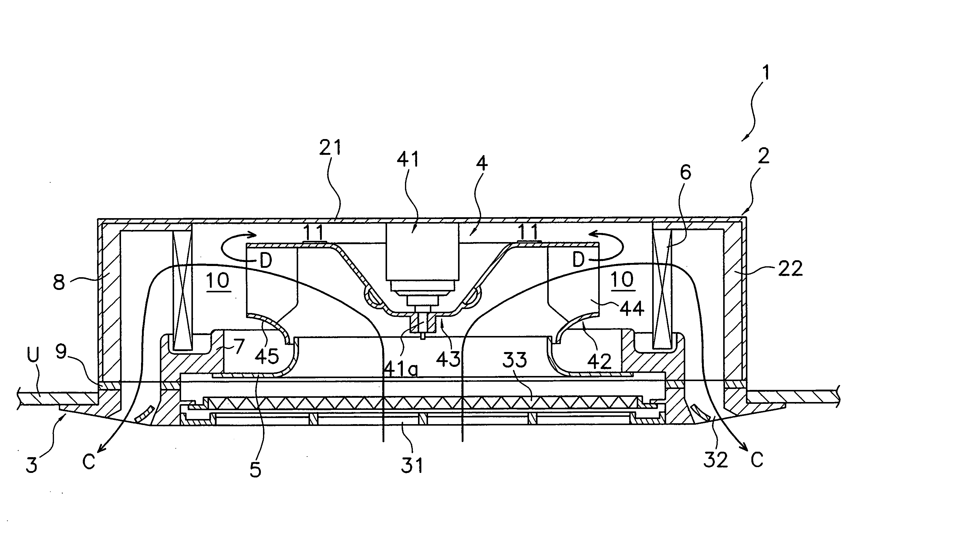
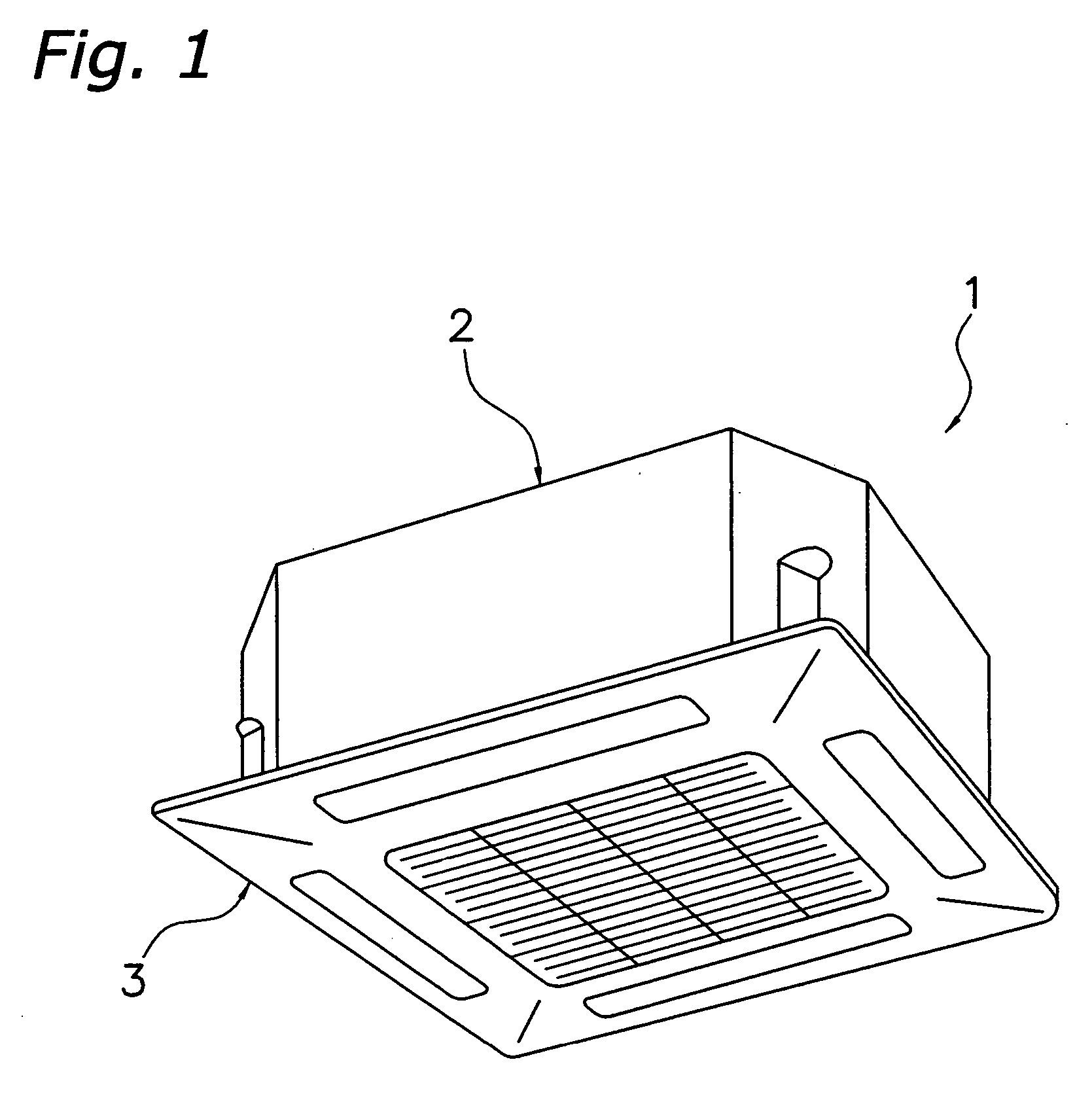
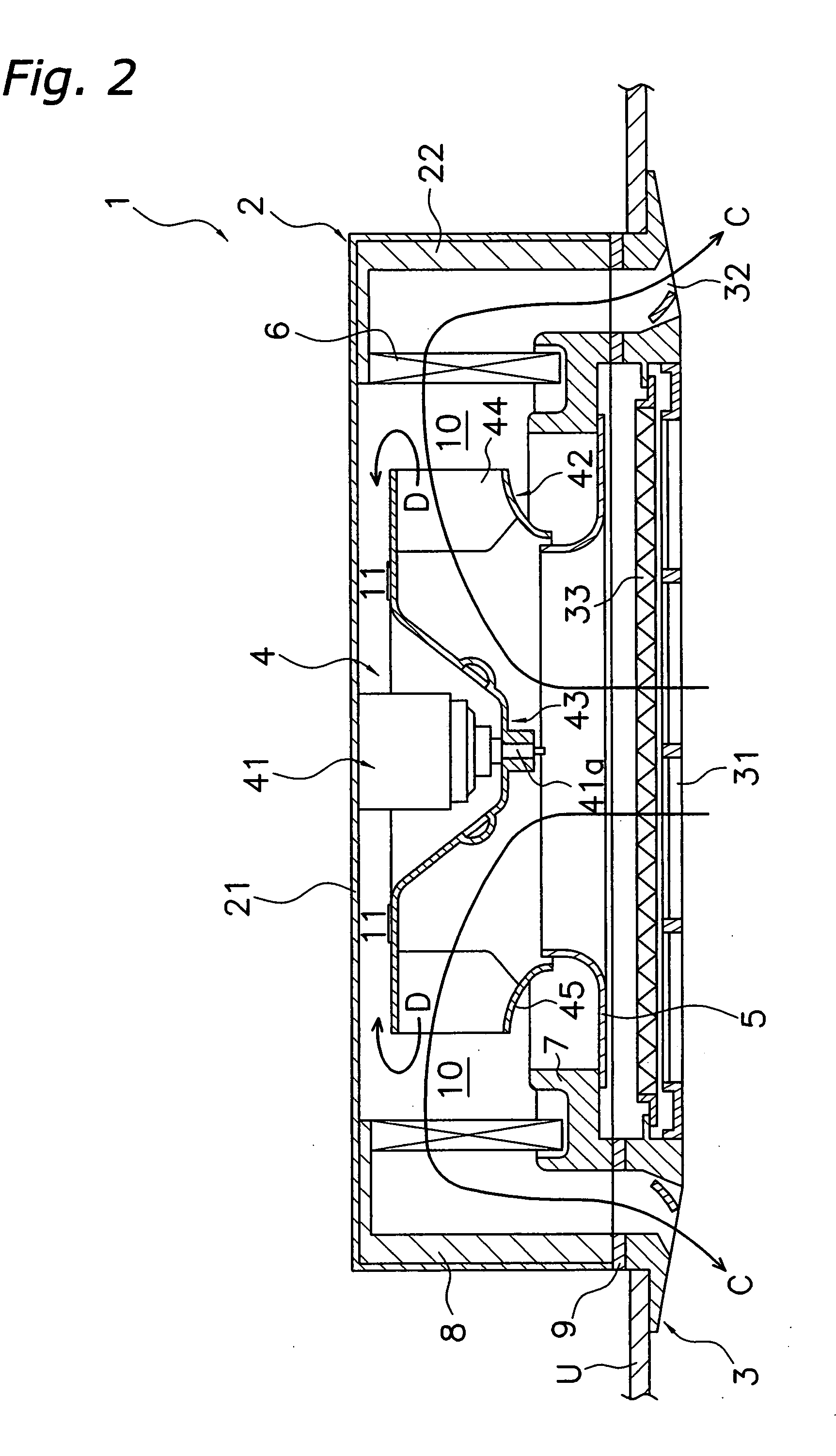
[0045]FIG. 1 shows an exterior perspective view (ceiling is omitted) of an air conditioner 1 provided with a centrifugal fan 4 according to the first embodiment of the present invention. The air conditioner 1 is a ceiling embedded type, and includes a casing 2 that houses various constituent equipment therein, and a decoration panel 3 arranged on the lower side of the casing 2. Specifically, the casing 2 of the air conditioner 1 is arranged and inserted in the opening formed in a ceiling U in the air conditioned room, as shown in FIG. 2. Furthermore, the decoration panel 3 is fitted into the ceiling U opening.

[0046] The casing 2 has a top plate 21, and a side plate 22 that extends downward from the peripheral edge part of the top plate 21.

[0047] The centrifugal fan 4 is arranged inside the casing 2. The centrifugal fan 4 is a turbofan, and has a fan motor 41 (electric motor) provided at the center part of the top plate 21 of ...

second embodiment

[0074] Although the air guide 52 of the motor cooling mechanism 51 in the first embodiment is provided on the lower surface side of the hub 43, it may also be provided on the upper surface side. Specifically, a fan motor cooling mechanism 151 of a centrifugal fan 104 built into an air conditioner 101 of the present embodiment has, as shown in FIG. 8 through FIG. 10, cooling air holes 143a formed in the hub 143 of the centrifugal fan 104, and an air guide 152 provided corresponding to the cooling air holes 143a.

[0075] The cooling air hole 143a is a hole provided in the hub 143 for guiding to the vicinity of the fan motor a portion of the air blown out toward the outer peripheral side by the turbo impeller 142, the same as in the first embodiment. In the present embodiment, the cooling air hole 143a is a long hole and a plurality thereof (five holes in the present embodiment) are formed arrayed concentrically with the hub 143.

[0076] In addition, in the present embodiment, the air gu...

third embodiment

[0077] In the first and second embodiments, the air guides 52, 152 of the fan motor cooling mechanisms 51, 151 were formed integrated with the hub 43, 143; however, they may also be provided in the hub cover, the same as the motor cooling mechanism 951 in the conventional example. Specifically, a fan motor cooling mechanism 251 of a centrifugal fan 204 built into an air conditioner 201 of the present embodiment includes, as shown in FIG. 11 and FIG. 12, cooling air holes 243a formed in a hub 243, and a volute blade-shaped guide blade 252 (air guide) provided in a hub cover 246. The hub cover 246 is fixed so that it rotates integrated with the hub 243 using a screw and a positioning pin, the same as the hub cover 946 in the conventional example.

[0078] The guide blade 252 is a plurality (two in the present embodiment) of volute blades that are inclined rearward with respect to the rotational direction (R direction) of the hub 243. Thereby, unlike the guide blade 952 of the fan motor ...


PUM


Abstract

The present invention obtains a desired cooling effect in a fan motor as well as suppresses any increase in the noise level in a centrifugal fan that sucks in air from the rotary shaft direction and blows out air in a direction that intersects the rotary shaft, and in an air conditioner provided therewith. The centrifugal fan of the air conditioner comprises a fan motor, a hub, a plurality of blades, and an air guide. The hub has cooling air holes, and is coupled to and rotationally driven by a shaft of the fan motor. The air guide guides a portion of the blown out air to the vicinity of the fan motor, cools the fan motor, and then guides the air flow so that the revolving direction velocity decreases when that air is blown out from the cooling air holes to the side of the hub opposite the fan motor.

Description

FIELD OF THE INVENTION [0001] The present invention relates to a centrifugal fan and an air conditioner provided therewith, and more particularly relates to a centrifugal fan that sucks in air from the rotary shaft direction and blows out air in a direction that intersects the rotary shaft, and an air conditioner provided therewith. RELATED ART [0002] Conventionally, centrifugal fans provided in air conditioners and the like have been designed to promote cooling of fan motors in order to prevent overheating of fan motors during operation. [0003] The following explains a conventional ceiling-embedded air conditioner provided with a conventional centrifugal fan that has a fan motor cooling mechanism to promote cooling of the fan motor of the centrifugal fan. [0004] The air conditioner includes a casing that houses various constituent equipment, and a decoration panel arranged on the lower side of the casing. An air inlet is provided at the approximate center of the decoration panel. T...

Claims


Application Information

Patent Timeline
Patent Type & Authority Applications(United States)
IPC IPC(8): F24F1/0022F04D25/08F04D29/28F24F1/0047F24F1/0063
CPCF04D25/082F04D29/282F24F1/0022F24F2001/0037F24F1/0007F04D29/281F24F1/0047F24F1/0063F04D29/5806F04D29/28F04D29/58
Inventor SANAGI, TSUNEHISA
Owner DAIKIN IND LTD
Why Eureka
Try Eureka