Latch device

a technology of latching device and latching plate, which is applied in the direction of fastening means, carpet fasteners, mechanical devices, etc., can solve the problems of not being completely satisfied, and achieve the effect of preventing improper operation, stable positional relation, and suppressing friction of the corresponding portions

Inactive Publication Date: 2005-03-22
NIFCO INC
View PDF11 Cites 37 Cited by
  • Summary
  • Abstract
  • Description
  • Claims
  • Application Information

AI Technical Summary

Benefits of technology

Improvements especially reside in that both sides of the cam grooves are formed in the same shape, and that the pin member is held in the upright position to be able to swing at the other end of the case through the intermediate portion (the whole pin member swings by the predetermined load around the intermediate portion), so the torsion force of the pin edge such as the conventional device is not used in the process of switching operations. Consequently, this structure prevents the pin member from forcibly deforming with long-term usage, so that the operational defect can be prevented. Operational sounds can be reduced in several degrees as compared to the conventional devices to thereby provide high-grade sense. Also, in the molding and processing of the latch member and the pin member, both sides of the cam grooves have the same shape, or symmetrical shape, so that the accuracy of the processing can be easily ensured, and the main causes for operational defect and yield rate decline due to relative dimensional error between the members can be improved.
Namely, the case includes elastic supporting pieces, etc. for supporting the U-shaped intermediate portion of the pin member with the predetermined pressure, and vertical ribs which limit the U-shaped side portions of the pin member with respect to the corresponding inner side faces. In this structure, for example, the elastic supporting pieces allow the pin member to swing while holding in the upright position, and the vertical ribs control the movements of the U-shaped side portions of the pin member to maintain a stable positional relation between edges and cam grooves.
In the pin member, the U-shaped side portions are pressed to contact with the corresponding inner side faces of the case, and each edge of the U-shaped side portions projects in a non-contact state with the groove bottom face relative to the corresponding cam grooves. The U-shaped side portions prevent the pin member from improperly swinging due to external vibration, etc. by contact pressures of the U-shaped side portions, and also prevent the improper operations. The edges of the U-shaped side portions come to the non-contact state with the groove bottom faces of the cam grooves, so that the friction of the corresponding portions can be suppressed and the operating sound when the operation is switched can be reliably prevented.
The latch member is composed of a sliding member including the cam grooves and an opening provided on the upper side from the cam grooves and being able to slide in order to be switched between the release position and the engagement position; and a latch claw pivoted on the sliding member and projecting from the opening such that the striker is prevented from being released or removed. Also, the latch member is generally fitted inside the case in the release position. This prevents the latch member from projecting from the case in the release position as little as possible, and keeps the appearance satisfactory.

Problems solved by technology

However, it is not yet completely satisfied from the following perspective.

Method used


Image

  • Latch device
  • Latch device
  • Latch device

Examples


Embodiment Construction

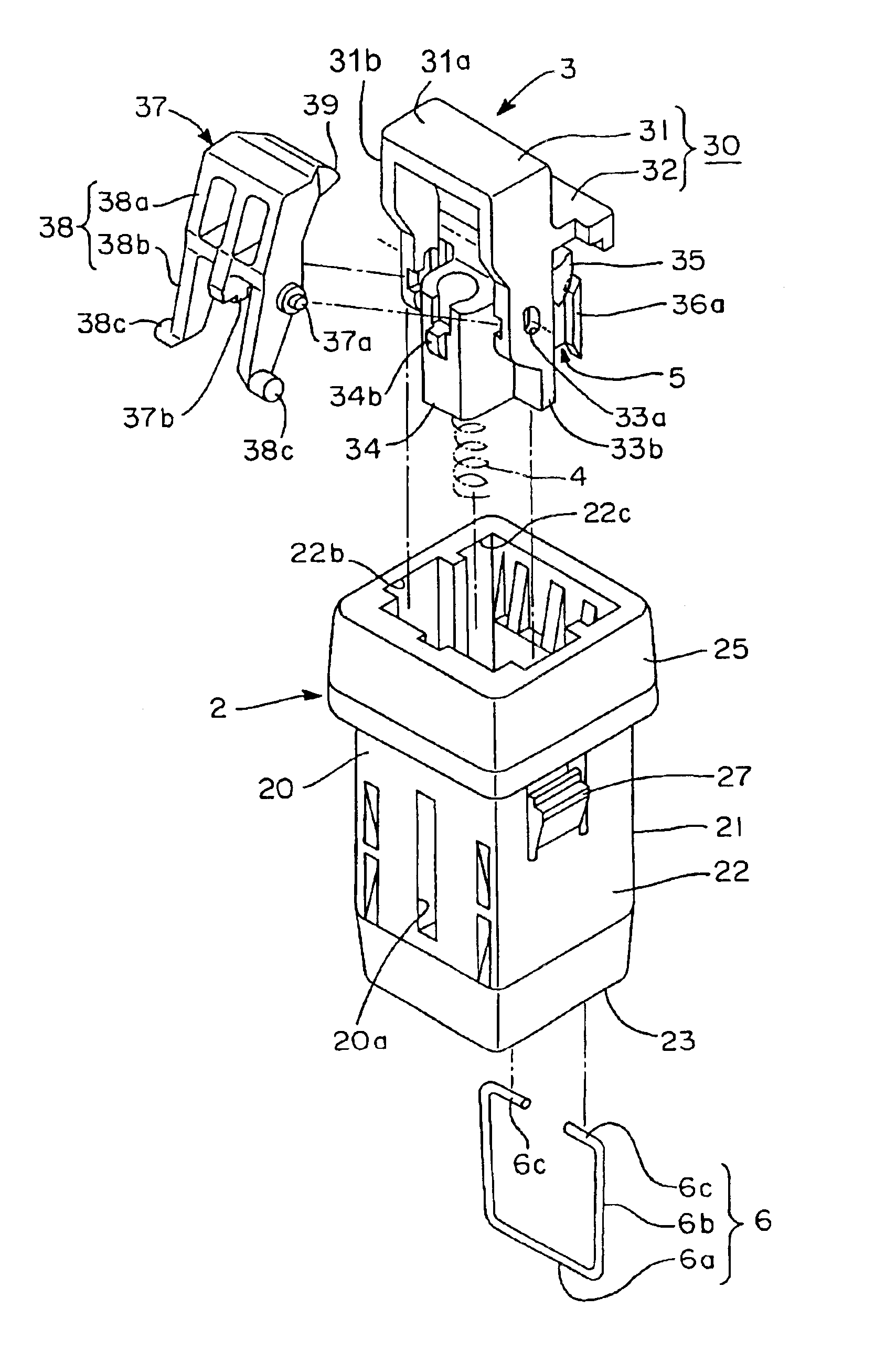
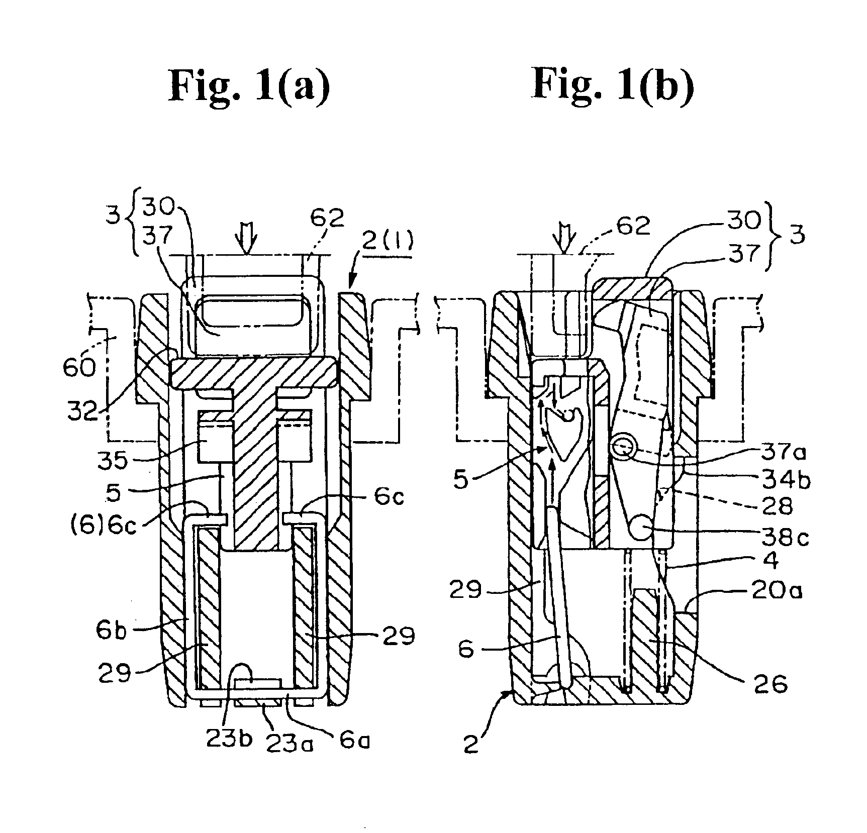
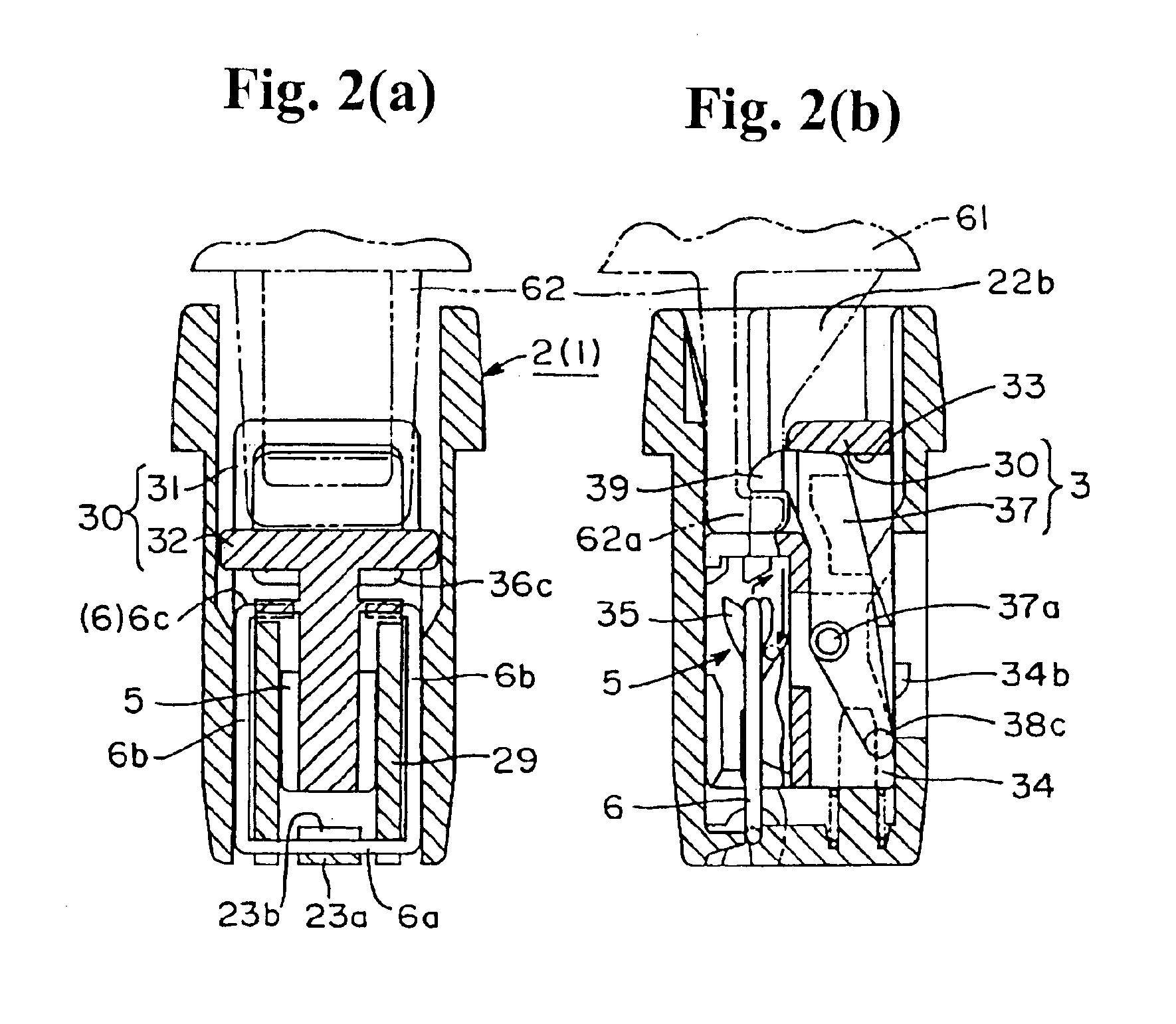
The embodiments of the present invention are explained based on the drawings. FIGS. 1(a)-1(b) through FIGS. 7(a)-7(e) show the latch device applied to the present invention. FIGS. 1(a)-1(b) and FIGS. 2(a)-2(b) show the device operation. FIGS. 1(a) and 2(a) are views sectioned generally along 1(a) and 2(a) line in FIG. 3(a), and FIGS. 1(b) and 2(b) are views sectioned generally along 1(b) and 2(b) line in FIG. 3(a). FIGS. 3(a)-3(d) show the device structure, wherein FIG. 3(a) is a top plan view, FIG. 3(b) is a front view, FIG. 3(c) is a view in which a case in FIG. 3(a) is sectioned only along line 3(c)—3(c) in FIG. 3(a), and FIG. 3(d) is a bottom view. FIG. 4 is a schematic structural view showing the exploded condition.

FIGS. 5(a)-5(f) show the case and the spring member, wherein FIGS. 5(a) and 5(b) are a top plan view and a bottom view of the case, FIGS. 5(c) and 5(d) are partly cut front view and side view, FIG. 5(e) is a cross sectional view taken along line 5(e)—5(e) in FIG. 5(a...


PUM


Abstract

A latch device engages and releases a striker by push-and-push operations. The latch device includes a case having an opening for receiving the striker therethrough, a latch member disposed inside the case and being able to be switched between an engagement position where the striker is prevented from being removed and a release position where the striker can be removed, a spring member for urging the latch member to the release position, generally heart-shaped cam grooves symmetrically provided on two sides of the latch member, and a pin member having a general U-shape and disposed inside the case. The pin member includes a U-shape intermediate portion disposed on a side opposite to the opening of the case, and edges formed at U-shape side portions. The edges project toward each other to engage and trace the cam grooves.

Description

BACKGROUND OF THE INVENTION AND RELATED ART STATEMENTThe present invention relates to a latch device used, for example, when a movable member such as a lid and so on is detachably engaged with a box-like base member, and formed of a push-push engagement mechanism (this can be referred to as a push-lock and push-open mechanism), wherein a striker is engaged by the first pushing operation, and is released by the next pushing operation.FIGS. 8(a)-8(b) and 9 are latch devices disclosed in Japanese Utility Model Publication No. 61-163870 (FIGS. 1-8) and Japanese Patent No. 3126992 (FIGS. 1-12). Each latch device 70, 80, for example, is attached to a box-like base member 60, and is formed of a push-and-push engagement mechanism which engages a striker 62 provided on a movable member 61 when the movable member 61 is moved from an open position to a closed position, and releases the engagement by a next pushing operation of the movable member 61. In these mechanisms, the latch device 70 in ...

Claims


Application Information

Patent Timeline
Patent Type & Authority Patents(United States)
IPC IPC(8): E05C19/00E05C19/02
CPCE05C19/022Y10S292/04Y10T292/0889Y10T292/702E05C19/02
Inventor UEKI, YASUSHI
Owner NIFCO INC
Why Eureka
Try Eureka