
Seat structure for vehicle

Inactive Publication Date: 2005-03-22
HONDA MOTOR CO LTD
View PDF18 Cites 44 Cited by
  • Summary
  • Abstract
  • Description
  • Claims
  • Application Information

AI Technical Summary

Benefits of technology

Accordingly, an object of the invention is to provide a seat structure for a vehicle which enables readily forming a box container (i.e., a box-like space which may be used for storing, placing, etc., articles, belongings, and so forth) and to increase the size of the box container.
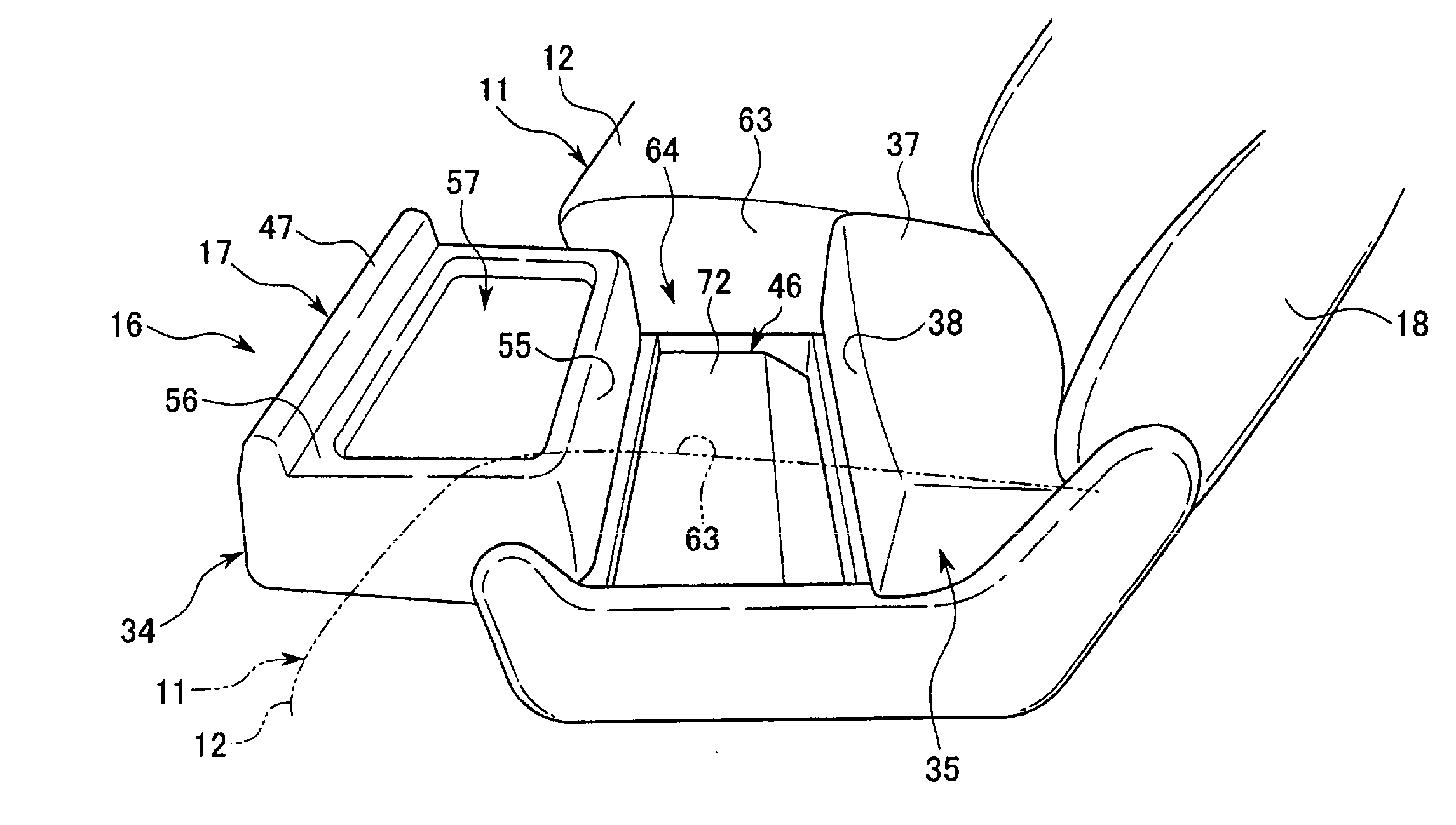
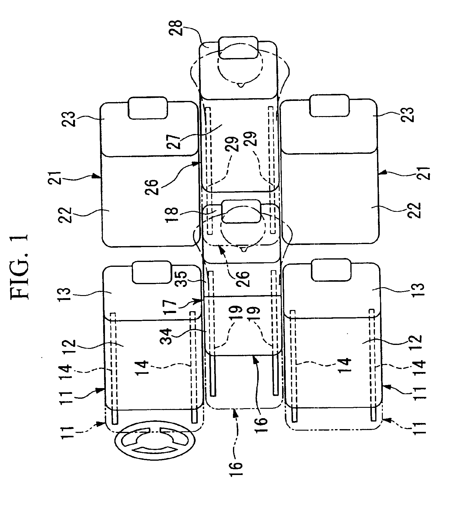
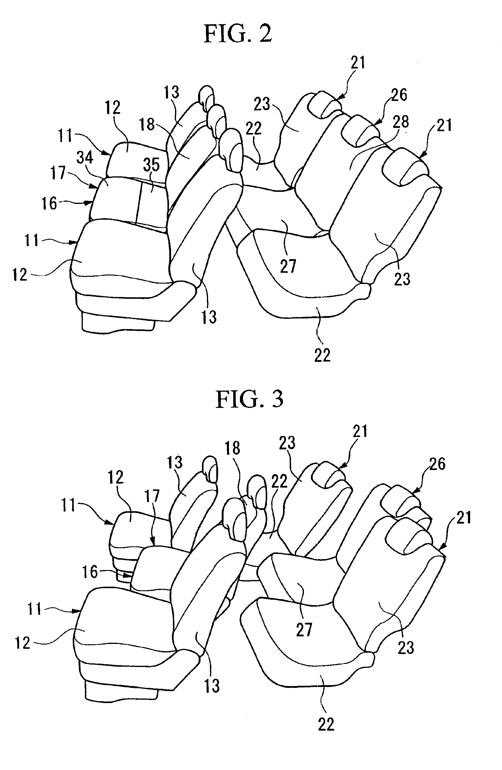
According to the above seat structure for a vehicle, when the front divided member of the seat cushion of the center seat is moved in the forward direction, the box container having an opened top is formed by the rear surface of the front divided member, the front surface of the rear divided member, and the side surface of the seat cushion of each of the pair of side seats facing the center seat. Accordingly, it is only necessary to move the front divided member to form the box container, and it is not necessary to remove the seat cushion each time. Also, since the right and left side surfaces of the box container are formed by the side surface of each of the right and left side seats, it becomes possible to increase the width of the box container as compared to a case where the right and left side surfaces of the box container are formed by a part of the center seat.
According to the above seat structure for a vehicle of the third aspect of the invention, use of the tray part by the passengers sitting on the right and left side seats may be further improved when the center seat is slid in a backward direction until it reaches a position where the front end portion of the tray part, after inversion of the front divided member, aligns with the front end portion of the pair of the side seats. Also, the front divided member of the center seat in a front rotated state does not interfere, for example, when passengers switch their seats between the right and left side seats.
According to the above seat structure for a vehicle of the fourth aspect of the invention, a storing space for a vehicle is increased since the second box container is provided below the first box container and is readily used by opening the bottom structure member which forms the bottom surface of the first box container.

Problems solved by technology

However, if a box container with an open top is formed by removing a center portion of a seat cushion as described above, the center portion of the seat cushion must be removed every time the box container is formed to place belongings, etc., and this is very troublesome for the driver and the passengers of a vehicle.
Also, there is a tendency for the size of the box container to be insufficient since the space is substantially formed by the rest of the seat cushion from which a part of the center portion is removed.

Method used


Image

  • Seat structure for vehicle
  • Seat structure for vehicle
  • Seat structure for vehicle

Examples


Embodiment Construction

The invention summarized above and defined by the enumerated claims may be better understood by referring to the following detailed description, which should be read with reference to the accompanying drawings. This detailed description of particular preferred embodiments, set out below to enable one to build and use particular implementations of the invention, is not intended to limit the enumerated claims, but to serve as particular examples thereof.

Hereinafter, the seat structure of a vehicle according to embodiments of the present invention will be described with reference to the accompanying drawings. Note that the words “front”, “back (rear)”, “right”, and “left” used in the following explanation mean “front”, “back (rear)”, “right”, and “left” with respect to the body of a vehicle.

The seat structure for a vehicle according to this embodiment of the present invention is applied to a three-person seat structure including a pair of side seats which are disposed at the right and ...


PUM


Abstract

A seat structure for a vehicle which includes a pair of side seats disposed at right and left sides of the vehicle; a center seat disposed between the pair of side seats, the center seat including a seat cushion which includes a front divided member and a rear divided member; and a first box container having an open top. The first box container may be formed, when the front divided member is moved in a front direction, by a surface of the front divided member, a front surface of the rear divided member, and a side surface of a seat cushion of each of the pair of side seats facing towards the center seat.

Description

BACKGROUND OF THE INVENTION1. Field of the InventionThe present invention relates to a seat structure for a vehicle.2. Description of Related ArtAs examples of a technique relating to a seat structure for a vehicle, it has been known to make a center portion of a seat cushion to be separable from the main body thereof so that a box-like container having a space which may be used for storing and / or placing articles, belongings, etc. (hereinafter also referred to simply as a box container) may be formed being surrounded by the rest of the seat cushion with its top portion being open. Also, it has been known to dispose a cover member at the opening portion of the box container so that it may be freely opened and closed as disclosed in Japanese Unexamined Patent Application, First Publication No. Hei 2-220936, for example.However, if a box container with an open top is formed by removing a center portion of a seat cushion as described above, the center portion of the seat cushion must b...

Claims


Application Information

Patent Timeline
IPC IPC(8): B60N2/01B60N2/005B60N2/06B60N3/10B60N2/30A47C7/62B60N2/32B60R7/04
CPCB60N2/01B60N2/06B60N2/206B60N3/10B60R7/043B60N2/305B60N2205/35
Inventor KAYUMI, TETSUYASHIROSE, OSAMUWATANABE, SHINSUKENAKAMURA, YOSHINORIKOIKE, OHSUKE
Owner HONDA MOTOR CO LTD
Learn More