System and method for monitoring connections in a rail assembly

a technology of connecting system and rail assembly, which is applied in the direction of electrical programme control, program control, instruments, etc., can solve the problems of rail assembly shutting down to correct errors, system is unable to detect whether a given arm inserted into the receiver is correct for a particular job, and cannot determine if the arm is properly mounted

Active Publication Date: 2005-03-22
SYRON ENG & MFG
View PDF10 Cites 3 Cited by
  • Summary
  • Abstract
  • Description
  • Claims
  • Application Information

AI Technical Summary

Benefits of technology

Because each arm may have a unique arm code, it is possible to assign receiver codes for any given job based on the arm codes and therefore ensure that the attached arms are appropriate for both the rail assembly and the specific job being conducted by the rail assembly.

Problems solved by technology

However, because the end of the arm is encased in the receiver, it may be impossible to determine if the arm is properly mounted through a visual inspection of the connection.
Thus, it is possible to mount an arm that is incorrect for a given job into the receiver due to operator error.
If the job begins with an incorrect arm, the rail assembly may need to be shut down to correct the error.
Although sensors and / or mechanical keying systems may be incorporated into the rail assembly to detect whether the arm is fitted correctly into the receiver, currently known systems are unable to detect whether a given arm inserted into the receiver is correct for a particular job.
Thus, even though there are ways to determine whether the physical connection between the arm and the receiver is secure, there is currently no known way to determine whether the arm is correct for a particular job.

Method used


Image

  • System and method for monitoring connections in a rail assembly
  • System and method for monitoring connections in a rail assembly
  • System and method for monitoring connections in a rail assembly

Examples


Embodiment Construction

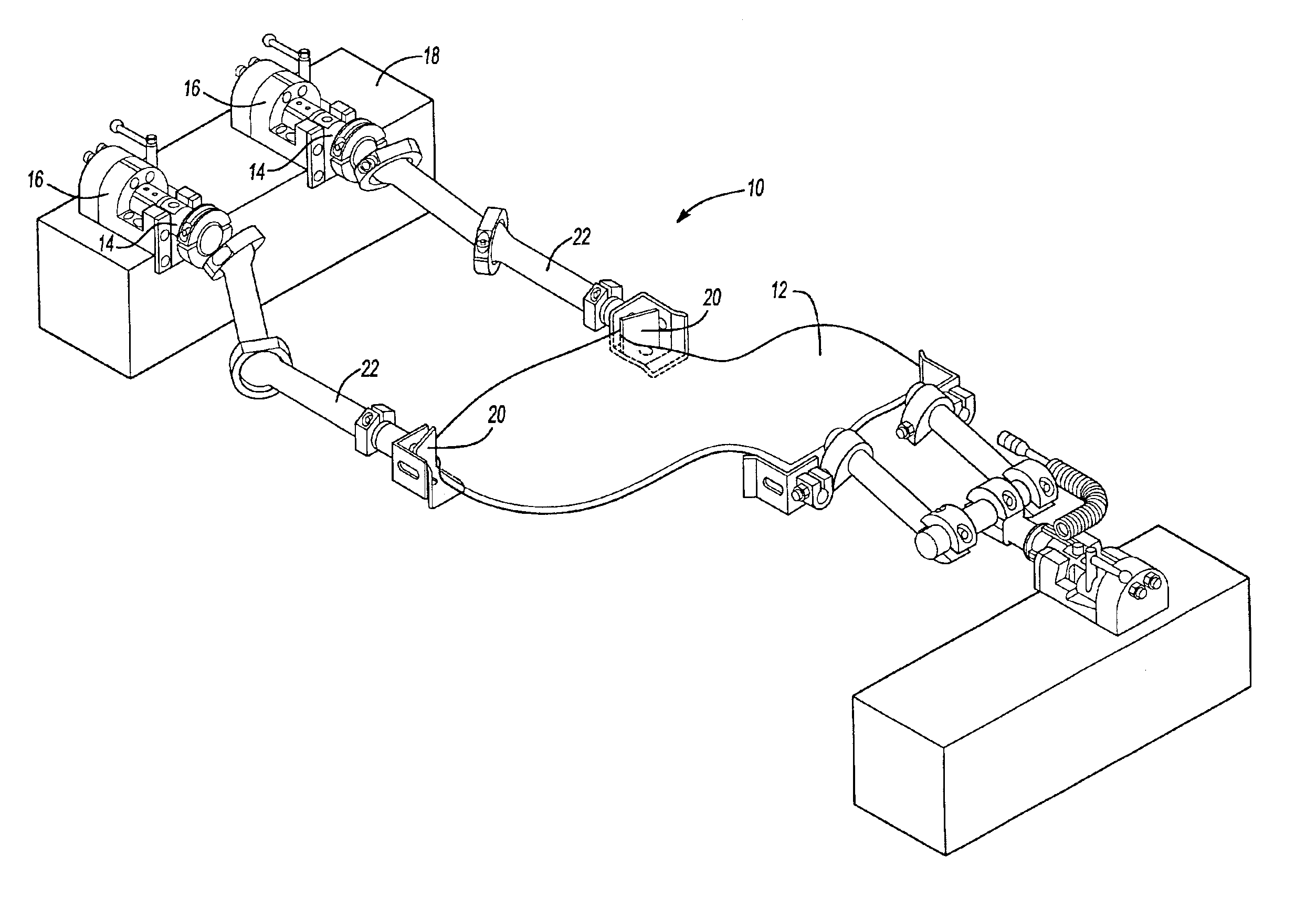
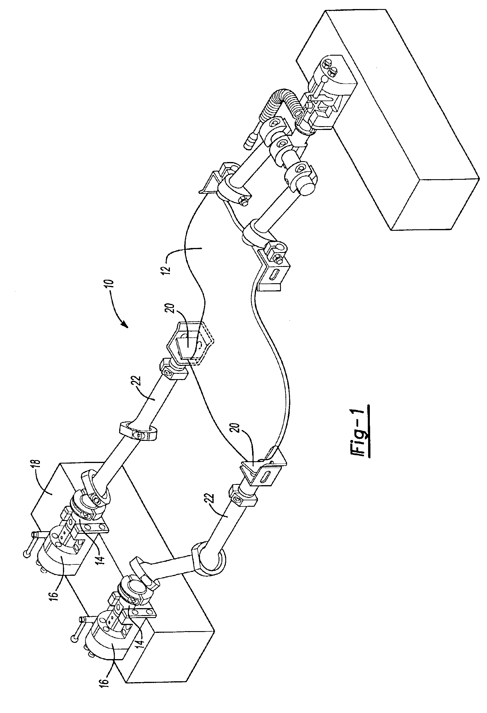
FIG. 1 illustrates one embodiment of a rail assembly 10 for gripping and moving an object 12. A multi-functional arm 14 is mounted in a receiver 16 that is attached to a rail 18. Although FIG. 1 shows only three receivers 16, it is to be understood that any number of receivers 16 can be attached to each rail 18 in the assembly 10. A ball jointed link 22 attached to the arm 14 is attached to a gripper 20 to grip the object 12. Although a ball jointed link 22 is described, it is to be understood that alternative joints are possible. Once properly mounted, the arm 14 is then locked in the receiver 16 with any known locking mechanism.

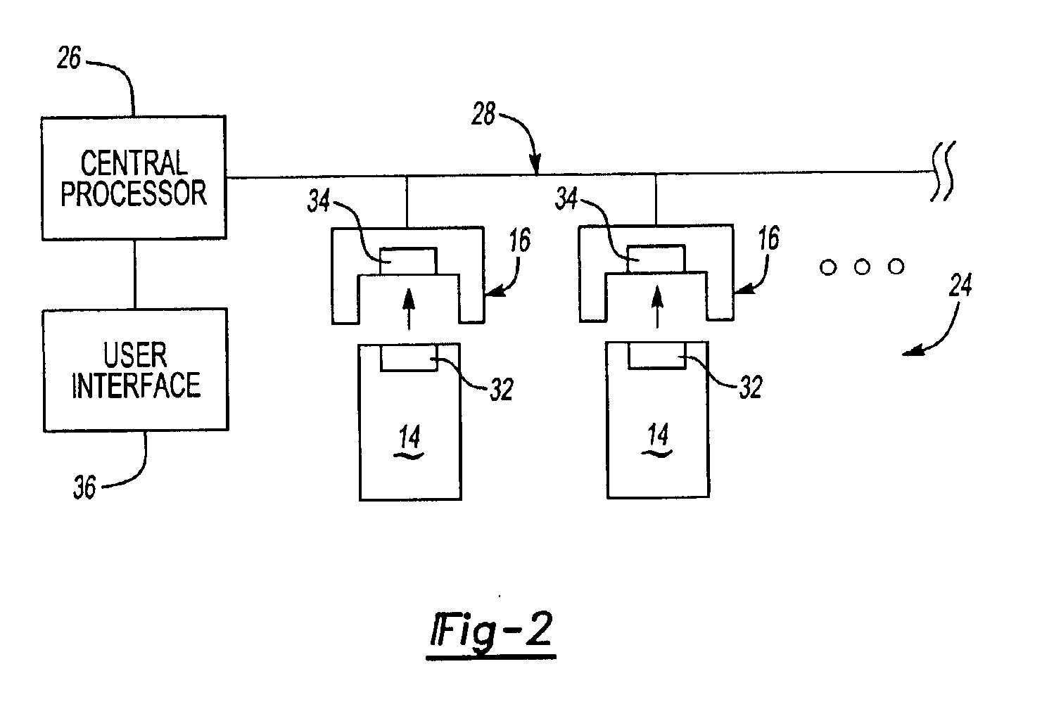
FIG. 2 is a block diagram illustrating a sensor system 24 that can be used in conjunction with the rail receiver assembly 10. The rail assembly 10 includes an arm 14 inserted into a receiver 16. The sensor system 24 is used to determined whether the arm 14 is inserted into the correct receiver 16 for the correct job. Generally, the sensor system 24 checks w...


PUM


Abstract

A system and method for a rail assembly ensures that the correct arms are connected to the correct receivers. Each arm has a unique associated arm code, and each receiver is assigned a unique receiver code based on the job to be performed by the rail assembly. After the arms are connected to the receivers, a processor compares the receiver code of each receiver with the arm code of the arm inserted in that receiver. If the two codes do not match, the system generates an alert to notify the user of the improper connection. The alert may be an audible alert, a visual alert, and/or an operational stoppage of the rail assembly.

Description

TECHNICAL FIELDThe present invention relates generally to a coding system for rail assemblies, and more particularly a system for detecting an improper connection between two components of a rail assembly.BACKGROUND OF THE INVENTIONRail assemblies are often used in manufacturing systems to move and grip objects. Known rail assemblies usually include removable arms mounted in receivers, which are attached to a rail. Commonly, a plurality of receivers are disposed along the length rail so that properly connected arms facilitate moving and gripping of objects.Once an arm is mounted in the receiver, it may desirable to determine whether the arm is properly connected into the receiver. However, because the end of the arm is encased in the receiver, it may be impossible to determine if the arm is properly mounted through a visual inspection of the connection.Further, different job processes may require different types of arms. Thus, it is possible to mount an arm that is incorrect for a g...

Claims


Application Information

Patent Timeline
Patent Type & Authority Patents(United States)
IPC IPC(8): B23Q17/00
CPCB23Q17/002Y10T483/12
Inventor JOHNSON, RICHARD R.
Owner SYRON ENG & MFG
Why Eureka
Try Eureka