
Flexible, self-aligning time and space switch fabrics

a time and space switch fabric, self-aligning technology, applied in the direction of time-division multiplexing selection, transmission, electrical equipment, etc., can solve the problems of memory technology scaling, limited time:space:time fabrics, and less practical selection methods of egress multiplexers

Inactive Publication Date: 2005-03-22
PMC-SIERRA
View PDF9 Cites 67 Cited by
  • Summary
  • Abstract
  • Description
  • Claims
  • Application Information

AI Technical Summary

Benefits of technology

"The invention is a switch fabric that allows for the efficient transfer of data between different devices. It includes multiple data switches that can rearrange data and transfer it to different destinations. The fabric also has high-speed serial links for connecting devices to the switches. The overall effect of this invention is a more efficient and flexible network for data transfer."

Problems solved by technology

This applies directly in the case of time and memory stages; in the case of space stages, the input ports must be able to direct their grains to specific egress ports—this is much less practical than the egress multiplexer selection method which is usually employed.
The motivation to move to multiple stage time and space fabrics is due to the inability of memory technology to scale to the aggregate bit rates imposed by N ports each supplying and consuming the bit rate represented by the grain group.
Whereas single stage memory fabrics are limited by the input / output capabilities of memory stages, time:space:time fabrics are limited by the ability to build practical space stages, as all N ports must converge at the space stage.
These fabrics have been limited in practice by their extra costs.
Also, the timing of the switch-over from one memory page to the next could not be timed.
This can be achieved in a variety of ways, but is always a significant difficulty in the design of a large composite fabric, as multiple units must be closely coordinated.

Method used


Image

  • Flexible, self-aligning time and space switch fabrics
  • Flexible, self-aligning time and space switch fabrics
  • Flexible, self-aligning time and space switch fabrics

Examples


Embodiment Construction

The invention will now be described in greater detail, with reference to the accompanying drawings.

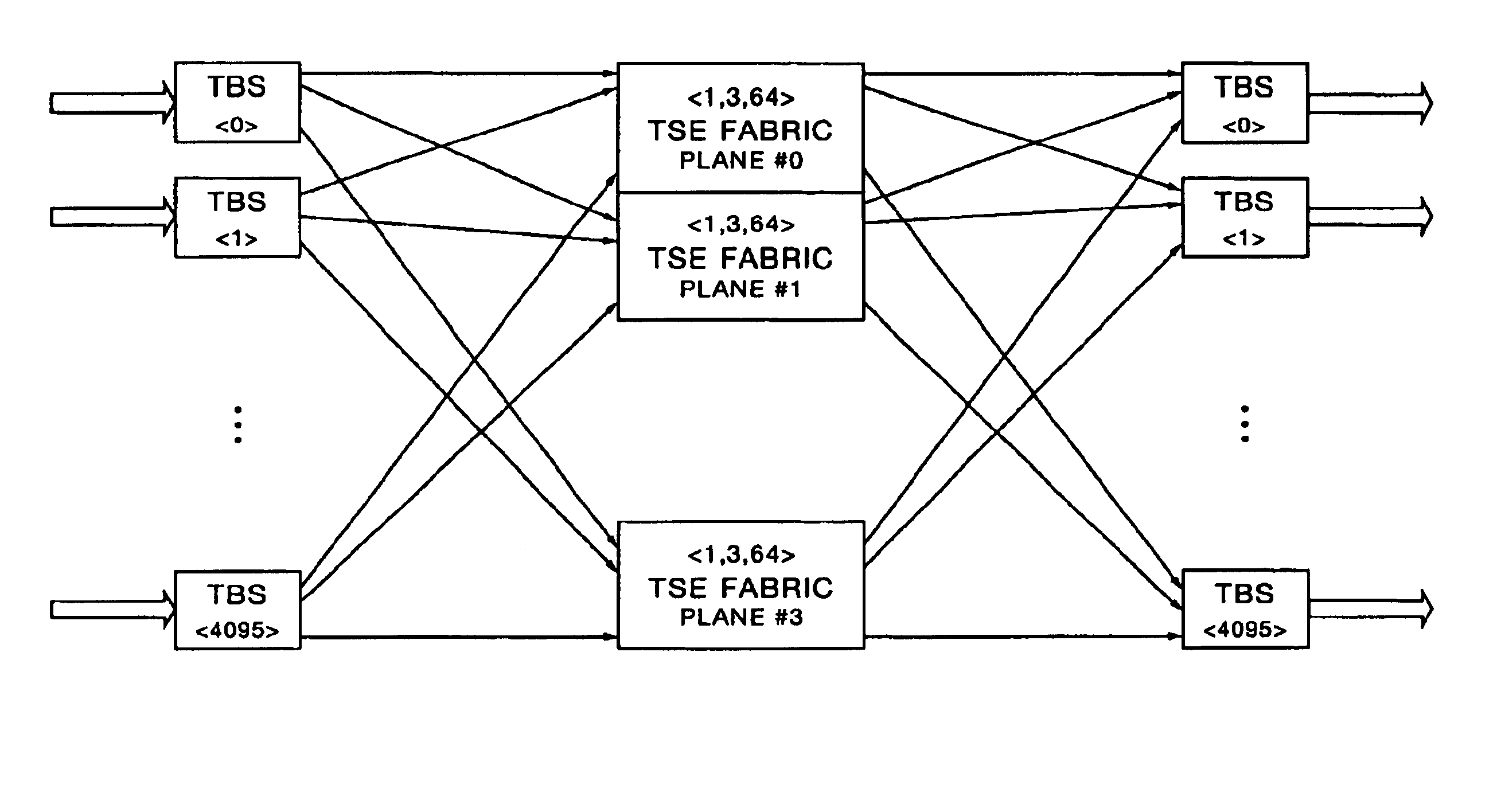
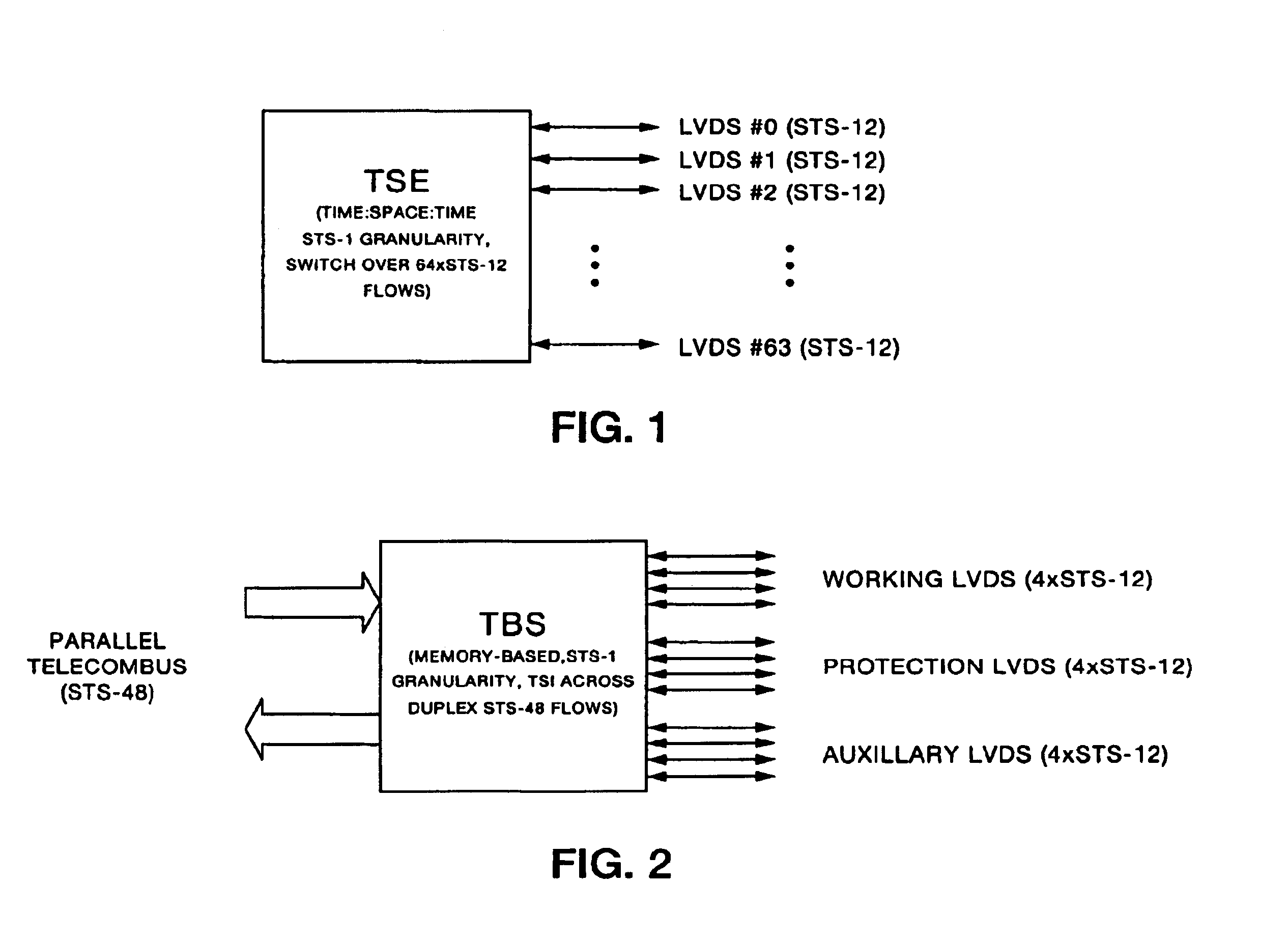
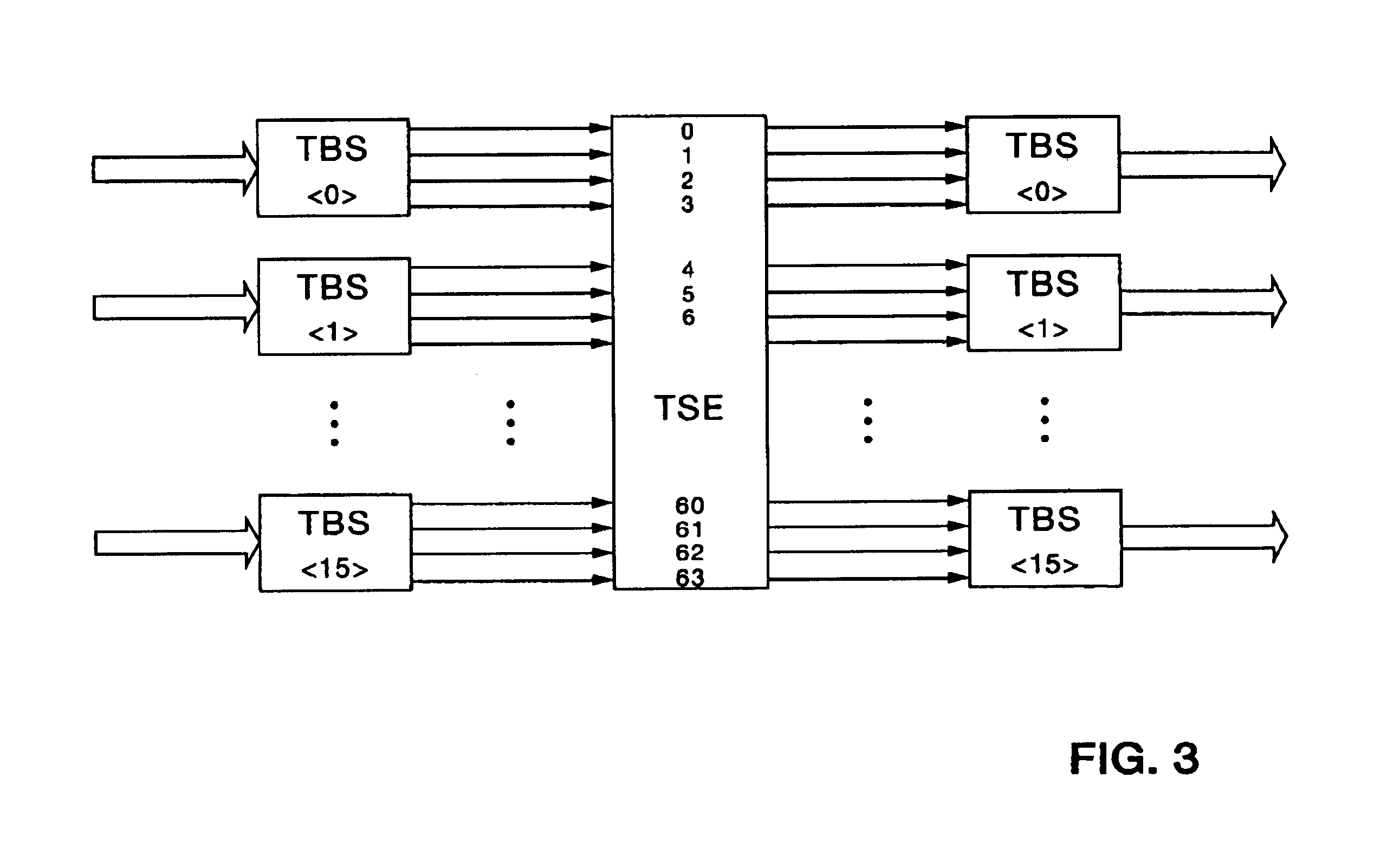
A “switching fabric” is the internal interconnect architecture used by a switching device, such as the FIG. 1 transmission switching element (TSE), to redirect data from one of the device's input ports to one of the device's output ports. The FIG. 1 TSE has 64 low voltage differential signal (LVDS) ports designated LVDS #0, LVDS #1, . . . LVDS #63. This is represented by the expression TSEports={64}. Each LVDS port carries one STS-12 signal link. The TSE has an STS-12 granularity time slot interchange (TSI) stage on each ingress and each egress STS-12 link. (“Granularity” represents the size of operations done by a process between communications events. A fine grained process may perform only a few arithmetic operations between processing one message and the next, whereas a coarse grained process may perform millions.) A 64×64 space switch is coupled between the TSE ingress and egress ...


PUM


Abstract

A time:space:time switch fabric incorporating an odd integer number of spatially distributed data switches and a plurality of spatially distributed data serializers. Each data switch has a first plurality of ingress ports, an equal plurality of egress ports, and a space switch for selectably interconnecting any one of the ingress ports to any one of the egress ports. Each data serializer has an input bus for receiving signals to be routed through the switch fabric, an output bus for outputting signals routed through the switch fabric, a plurality of egress ports selectably connectible to any one of the data switch ingress ports, and an equal plurality of ingress ports selectably connectible to any one of the data switch egress ports. The ingress / egress ports are characterized by:(A) p planes, where p is a power-of-two integer less than or equal to the number of data serializer ingress and egress ports;(B) s stages, where s is an odd integer number; and,(C) a depth d, where d is a power-of-two integer less than or equal to the number of data switch ingress and egress ports.

Description

TECHNICAL FIELDThis invention relates to high speed, time division multiplexed (TDM) signal switching via time and space switch fabrics in devices such as synchronous optical network (SONET) cross-connects, add-drop multiplexers, terminal multiplexors, etc.BACKGROUNDTime and space switching fabrics have been used for many years in a variety of switching and multiplexing devices including SONET cross-connects, SONET add-drop multiplexers, SONET terminal multiplexers, and digital signal-level 0 (DS0) switches. Time and space switching fabrics are common in essentially all telephony and SONET switching devices on the market today.There are three basic mechanisms used in time and space switching: 1) time switching stages, 2) space switching stages, and 3) combined time and space switching stages, which are referred to as multi-ported memory switches, or just memory switches. Switching fabrics are constructed by composing one or more stages of these three types of switching elements.Thes...

Claims


Application Information

Patent Timeline
Patent Type & Authority Patents(United States)
IPC IPC(8): H04Q11/06
CPCH04Q11/06H04Q2213/1302H04Q2213/1304H04Q2213/13214H04Q2213/13367H04Q2213/13322H04Q2213/1334H04Q2213/13341H04Q2213/1336H04Q2213/13292
Inventor HUGHES, ANDREW MILTONKONKIN, DOUGLASMCCROSKY, CARL DIETZMOK, WINSTONROE, JEFFREY SCOTTSAILOR, KENNETH EVERT
Owner PMC-SIERRA
Learn More