Electrically driven hair removal device

a hair removal and electric drive technology, applied in the direction of metal working devices, etc., can solve the problems of significant reduction of the illumination effect, and achieve the effect of increasing the operation convenience and utility value of such a devi

Inactive Publication Date: 2005-03-29
BRAUN GMBH
View PDF29 Cites 55 Cited by
  • Summary
  • Abstract
  • Description
  • Claims
  • Application Information

AI Technical Summary

Benefits of technology

In one preferred embodiment the required light is generated directly at the operating area of the device or is at least directly available there. This not only enables optimum illumination of the operating area, but also affords the possibility of using corresponding light signals, which can be generated for example by flashing, altering the brightness, changing the color and the like, to indicate operationally relevant properties or information to the user, without the latter having to avert his gaze from the actual operating area. Thus, by way of example, information about the contact pressure on the skin, the remaining rechargeable battery capacity or the like can be indicated to the user by corresponding light signals.
Such visualization of system properties directly in the user's field of view decisively increases the operational convenience and the utility value of such a device. A useful condition for such a type of indication, however, is a particularly reliable and complete transmission of the light signal into the user's field of view.
In order to obtain an intense system illumination, the illumination device has at least one optical wave guide, which is arranged on one operating element which is movable relative to another operating element and / or to the housing, and at least one light source, which is arranged on a housing section and whose light beams couple into the optical wave guide. If the light beams of the light source are coupled contactlessly via an air gap, the illumination of driven components can be implemented in a simple manner. Of course, the light source can also be arranged directly in at least one of the operating elements.
Particularly good visualization of the mechanical operating system with its operating elements that are moved relative to one another can be obtained with a low structural outlay if the illumination device emits stroboscopically pulsed light signals. In this case, an ideal possibility for representing the system dynamics is provided when the frequency of the light signals about + / −20% of the frequency of the movement of the operating elements. In this way, it is possible to generate still or, alternatively, very slowly moving images of a highly dynamic or high-frequency movement.

Problems solved by technology

The electrical light in this shaver is significantly darkened both by the lower blade and by the clipping foil, which significantly reduces the illumination effect.

Method used


Image

  • Electrically driven hair removal device
  • Electrically driven hair removal device
  • Electrically driven hair removal device

Examples


Embodiment Construction

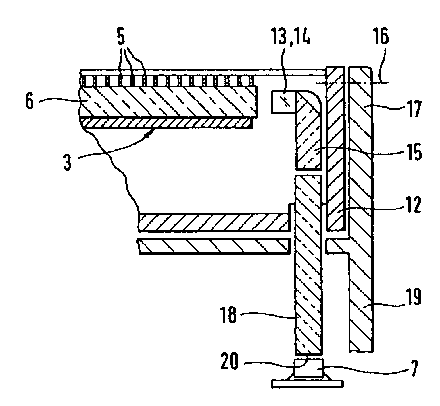
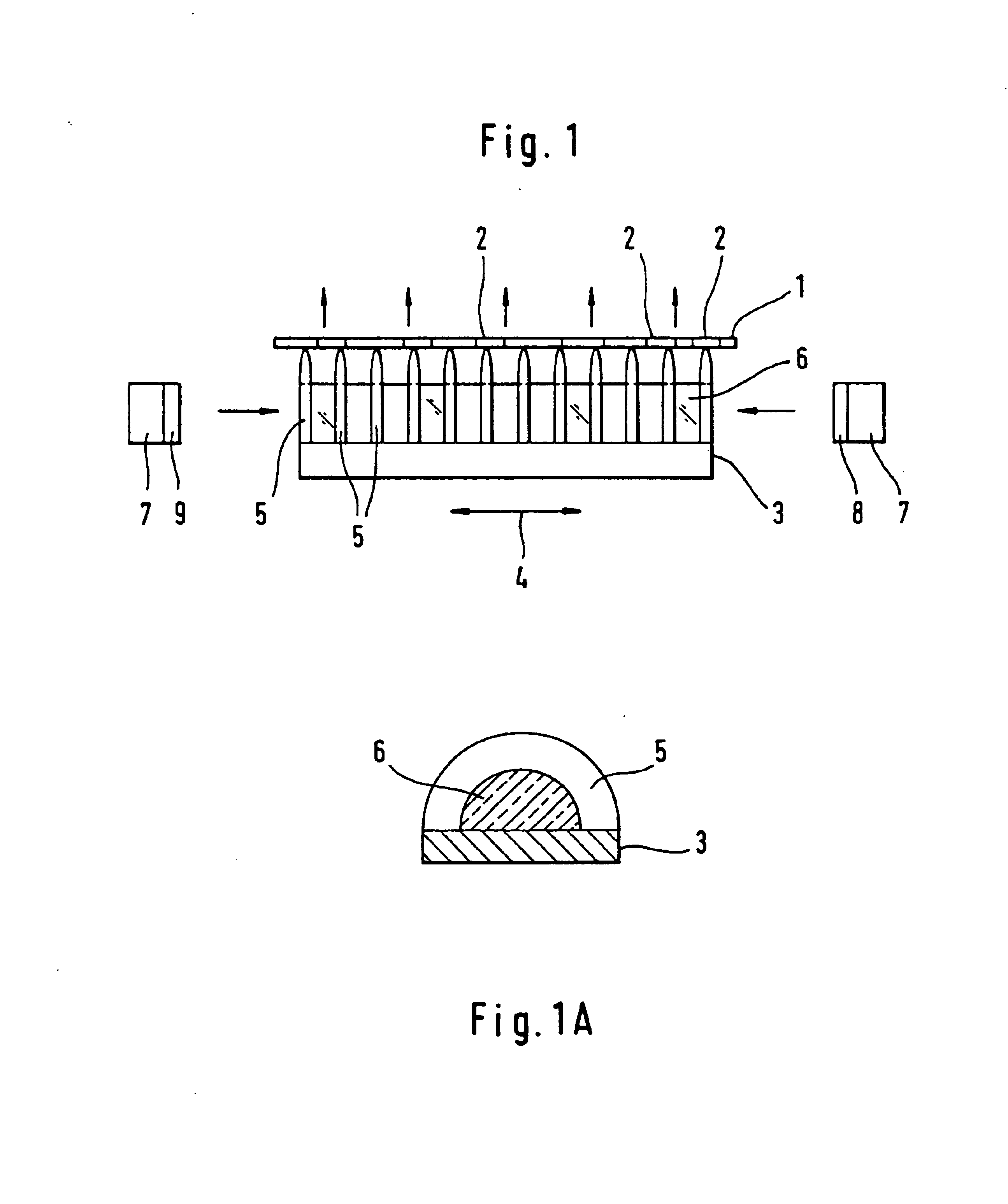
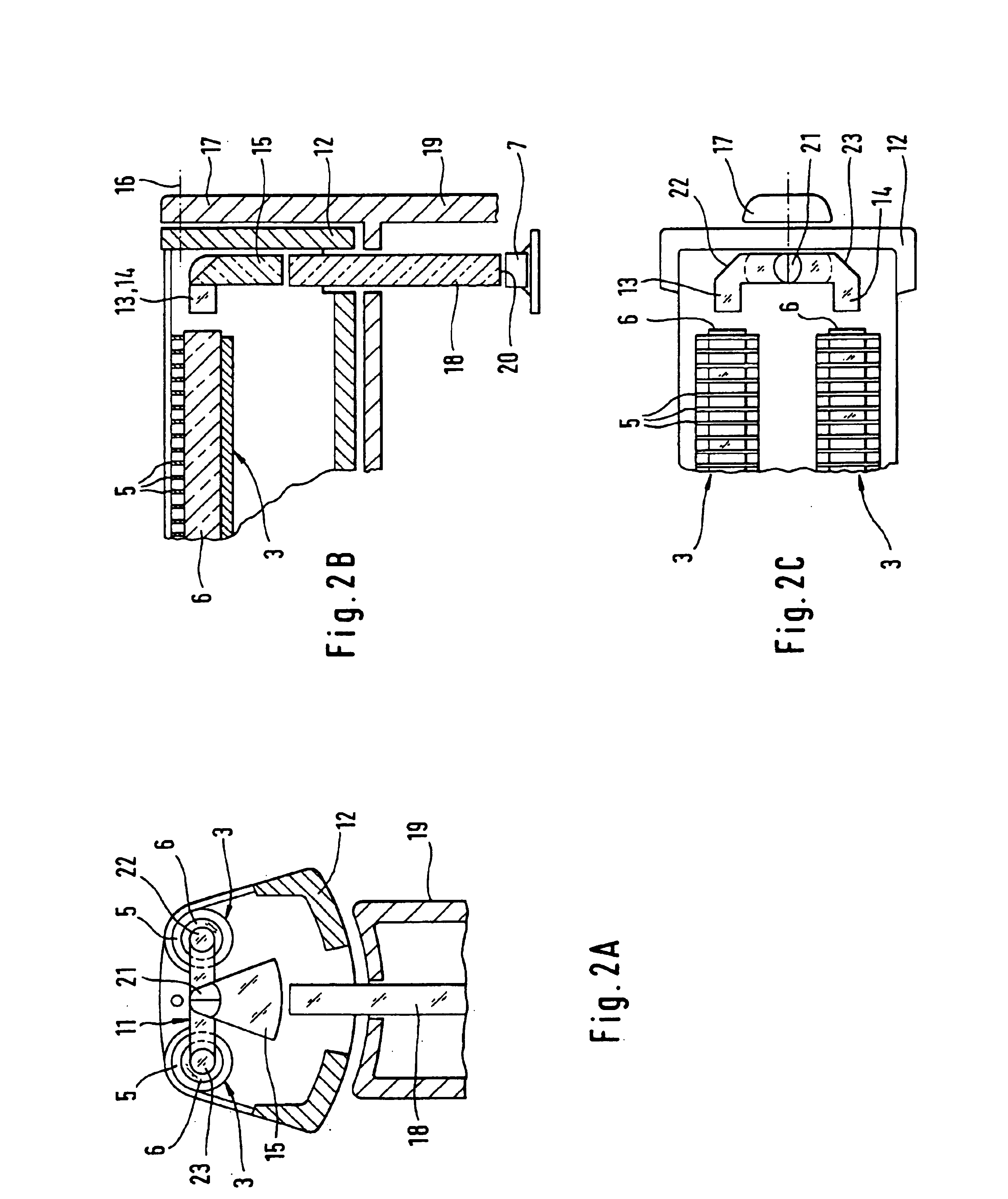
FIG. 1 shows a schematic sketch of a detail from a clipping head of an electric shaver. This clipping head essentially comprises, in a manner known per se, a clipping foil 1 with openings 2, which is stretched over a lower blade 3 which, as is indicated by the arrow 4, is driven in translatory oscillating fashion in a suitable manner. The lower blade 3 is designed as a so-called blade block with a multiplicity of blades 5 arranged in parallel in a row next to one another. The blade block or the blades 5 are under elastic prestress at the clipping film 1, so that hairs that are threaded into the openings 2 are clipped off between the hole edge of the corresponding opening 2 and the blade 5, whose oscillation amplitude is greater than the extent of the openings 2.

As can be gathered from FIG. 1A, in particular, the blades 5 have approximately the contour of half an annulus. An optical wave guide 6 having approximately a semicircular cross section is led through the blades 5. Said wave ...


PUM


Abstract

An electrically operated hair removing device, comprising a housing, an operating system connected to the housing for clipping and / or plucking hair, the system having at least two operating elements which are movable relative to one another and at least one of which is driven, and an illumination device for illuminating the operating system, the illumination device being integrated in at least one of the operating elements.

Description

TECHNICAL FIELDThe invention relates to an electrically operated hair removing device.Shavers, hair / beard clippers and epilation devices are examples of electrically operated hair removing devices. EP 0 069 468 A1 discloses a dry electric shaver that has a housing and a lower blade which is driven in translatory oscillating fashion and is situated below a clipping foil. Within the housing, an electrical lamp is arranged in a region below the lower blade that is adjacent to the clipping head, which lamp transilluminates both the lower blade and the clipping foil and thus illuminates the skin location to be shaved. The electrical light in this shaver is significantly darkened both by the lower blade and by the clipping foil, which significantly reduces the illumination effect. For this reason, a further embodiment of EP 0 069 468 A1 has an additional illumination arrangement outside the clipping head, which in turn is associated with an additional outlay.Therefore, the invention is ba...

Claims


Application Information

Patent Timeline
Patent Type & Authority Patents(United States)
IPC IPC(8): B26B19/46B26B19/38
CPCB26B19/46B26B19/382
Inventor BADER, RAOULGRADL, MATTIASHOTTENROTT, SEBASTIANJUNK, PETERKLEEMANN, CHRISTOFMEISS, MICHAELNEUMANN, UWEODEMER, MICHAELREHKLAU, ANDREASSTORKEL, JENSTOIVANEN, PETRIWINKLER, TILLWOLF, JURGEN
Owner BRAUN GMBH
Why Eureka
Try Eureka