Rotational float for rotating equipment

Inactive Publication Date: 2005-03-29
ALTEC INDS
View PDF17 Cites 10 Cited by
  • Summary
  • Abstract
  • Description
  • Claims
  • Application Information

AI Technical Summary

Benefits of technology

The present invention solves the above-described problems and provides a distinct advance in the art of side load protection systems for digger derricks and other rotating equipment. More particularly, the present invention provides a rotational float system that is

Problems solved by technology

Digger derricks and other rotating equipment are often subjected to excessive and undesirable side loading.
Side loading also often occurs when an auger-type digger coupled with the boom “corkscrews” into the ground due to the application of excessive pressure in driving the auger or when anchors are improperly installed.
Excessive side loading can cause damage or destruction of the digger derrick's boom, turntable, and rotation drive mechanism.
Improper installation of an anchor can also significantly reduce its pull-out strength.
If an operator forgets or otherwise fails to correctly follow the path of an anchor into the ground by manipulating the digging, boom extending/retracting, boom lowering/raising, and rotating functions, the anchor will tend to pull the boom to one side, exerting considerable side loading on

Method used


Image

  • Rotational float for rotating equipment
  • Rotational float for rotating equipment
  • Rotational float for rotating equipment

Examples


Example

The drawing figures do not limit the present invention to the specific embodiments disclosed and described herein. The drawings are not necessarily to scale; emphasis instead being placed upon clearly illustrating the principles of the invention.

DETAILED DESCRIPTION OF THE PREFERRED EMBODIMENTS

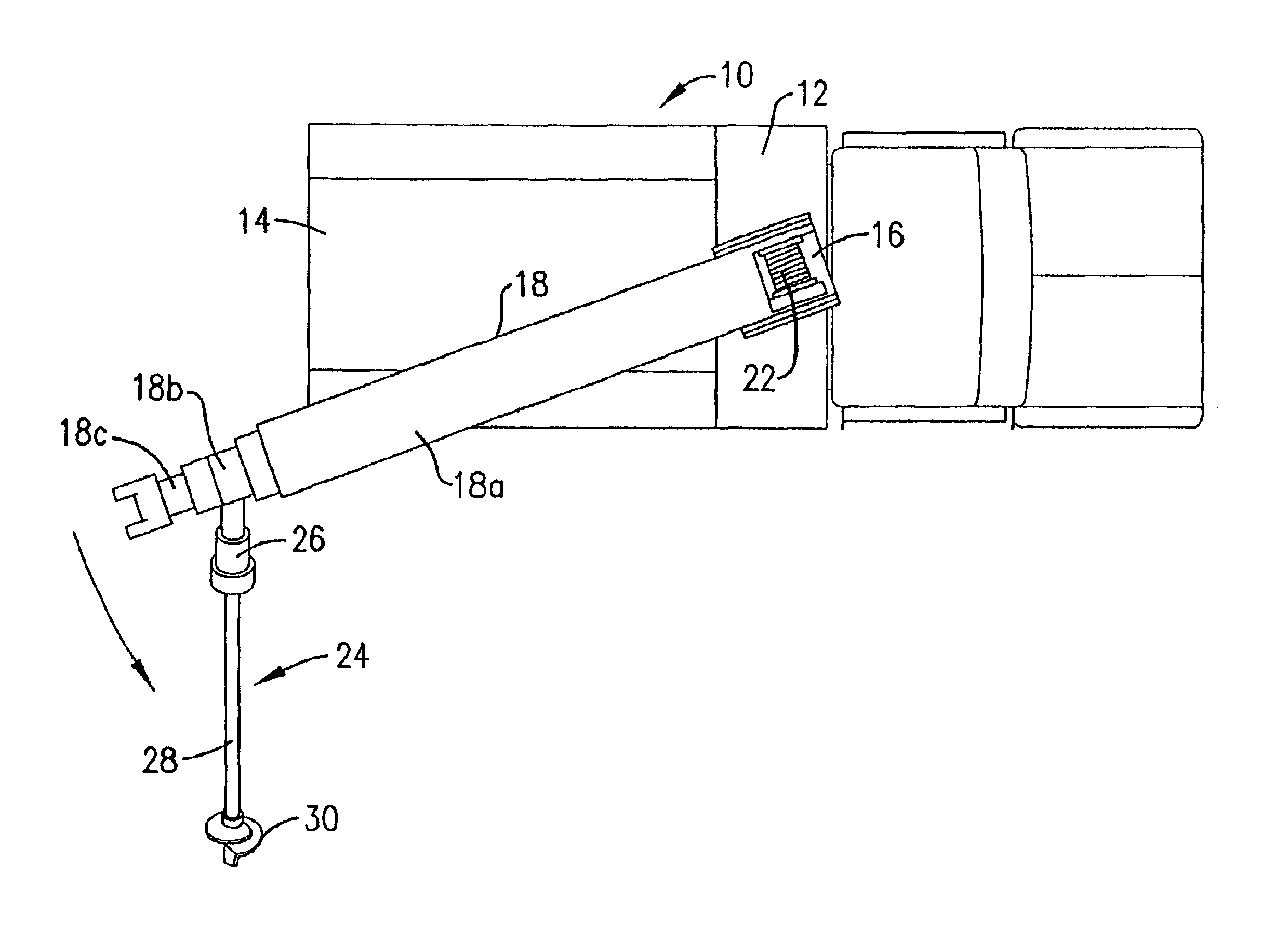
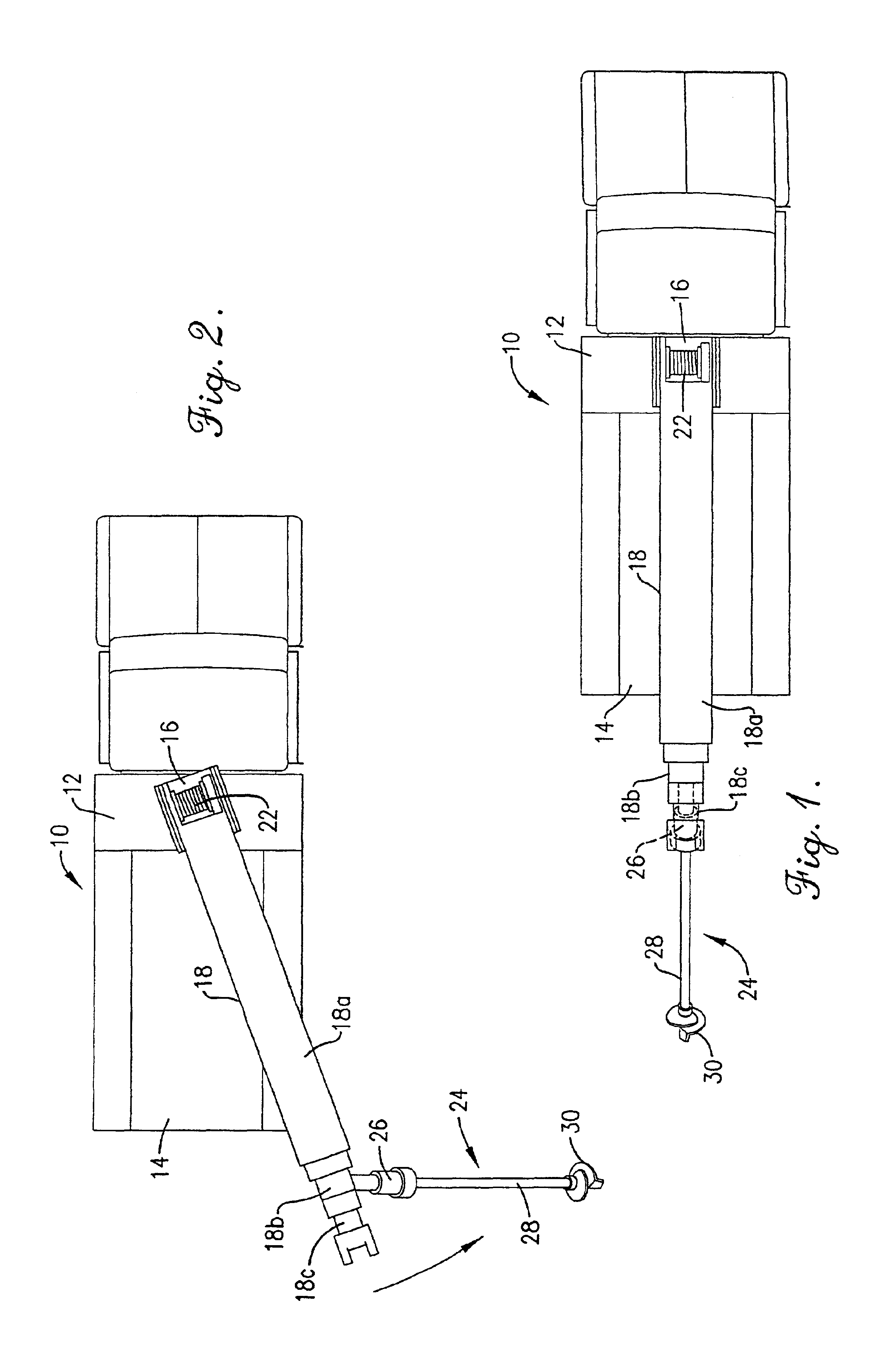
Turning now to the drawing figures, and particularly FIGS. 1 and 2, a conventional truck-mounted digger derrick 10 of the type with which the present invention is adapted for use is illustrated. The digger derrick 10 broadly includes a frame 12 mounted on a truck bed 14 that rotatably supports a turntable 16. An elongated boom 18 extends outwardly from the turntable 16 and is operable to rotate with the turntable 16.

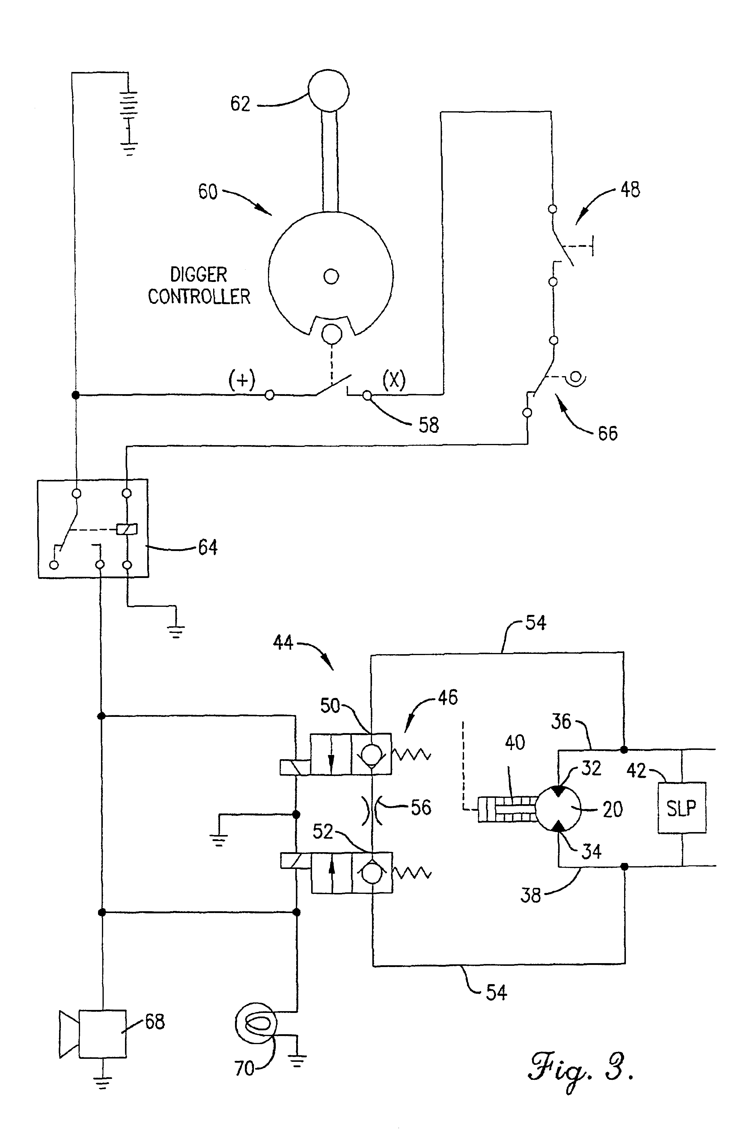
The turntable 16 and the boom 18 are rotatably driven by a hydraulic rotation motor 20 (FIG. 3) mounted to the turntable 16. The rotation motor 20 delivers rotational force to the turntable 16 through conventional drive linkage. The boom 18 may be pivoted up and down relative to th...


PUM


Abstract

A rotational float system (44) that is meant to be used with existing side load protection systems and that may be selectively operated to permit a digger derrick rotation motor (20) or other rotatable equipment to freely rotate toward a side load to ease operation of and prevent damage to the digger derrick (10) and to assist in the correct installation of screw anchors. The rotational float system (44) includes valve structure (46) interposed between the ports (32, 34) of a hydraulic rotation motor (20) and a control mechanism (48) for selectively opening and closing the valve structure (46). The valve structure (46) is normally biased to a closed position and the control mechanism (48) is normally open. When the control mechanism (48) is operated, it opens the valve structure (46) to connect the ports (32, 34) of the rotation motor (20) to one another. This allows the pressure of the hydraulic fluid present at each of the ports (32, 34) to equalize so that the rotation motor (20) may float or rotate toward any external side loads.

Description

BACKGROUND OF THE INVENTION1. Field of the InventionThe present invention relates to rotatable equipment such as digger derricks. In particular, the invention relates to a rotational float system that may be selectively operated to permit a digger derrick boom to freely rotate toward a side load to simplify operation of and prevent damage to the digger derrick.2. Description of the Prior ArtDigger derricks, cranes, and other types of rotating equipment are commonly used to perform many different jobs, including digging holes for utility poles and installing screw anchors for supporting the poles. Digger derricks are typically mounted to mobile utility vehicles and include a rotating turntable from which a boom extends. The boom may be raised, lowered, extended, and retracted to position its outboard end in various locations to perform digging or hoisting operations. Digger and auger assemblies may be coupled with the outer end of the boom for digging holes for utility poles and for ...

Claims


Application Information

Patent Timeline
IPC IPC(8): E21B7/02E02F9/08E02F9/12
CPCE02F9/128E21B7/023E21B7/022
Inventor DARLING, W. BRIANHENKE, HARLAN H.
Owner ALTEC INDS
Why Eureka
Try Eureka