Post-mix beverage dispenser for frothed beverages

a beverage dispenser and beverage technology, applied in the field of beverage dispensers, can solve the problems of a large number of pre-mix dispensers, and achieve the effect of substantial improvement of whipping gain

Inactive Publication Date: 2005-03-29
FOX DAVID
View PDF8 Cites 59 Cited by
  • Summary
  • Abstract
  • Description
  • Claims
  • Application Information

AI Technical Summary

Benefits of technology

In one embodiment, a jet or outlet is in fluid communication with a source of diluent and directed at a wall of a mixing chamber at an angle such that the diluent hits the wall tangentially, forming a swirling descending mass of diluent. A concentrate dispensing outlet in fluid communication with the source of concentrate is positioned to eject concentrate into the mixing chamber. When the concentrate contacts the swirling mass of diluent, turbulent mixing of the diluent and concentrate create the frothed or whipped beverage.
In another embodiment, a diluent jet or outlet is configured and positioned such so as to eject a stream of diluent therefrom and into the mixing chamber. Typically, the jet extends into the mixing chamber. A concentrate dispensing outlet, typically formed in the removable concentrate dispensing member, is oriented substantially directly at the diluent jet such that the streams of concentrate and diluent collide, causing turbulent mixing of the diluent and the concentrate to create the desired whipped beverage.
It has been found that the aforementioned arrangements allow the use of traditional dispensing heads which are modified only slightly. Furthermore, there is no need for air passageways to create venturi effects. Moreover, the whip-gain has been found to be substantially improved.

Problems solved by technology

However, when mixed with a diluent such as water or exposed to air, the combined beverage usually requires refrigeration to retard bacterial growth.
However, such pre-mix dispensers suffer from a number of disadvantages.
Another problem with all of these devices is that, due to their specialized design, they effectively served as a stand-alone dispenser often placed next to traditional carbonated beverage dispensing banks.

Method used


Image

  • Post-mix beverage dispenser for frothed beverages
  • Post-mix beverage dispenser for frothed beverages
  • Post-mix beverage dispenser for frothed beverages

Examples


Embodiment Construction

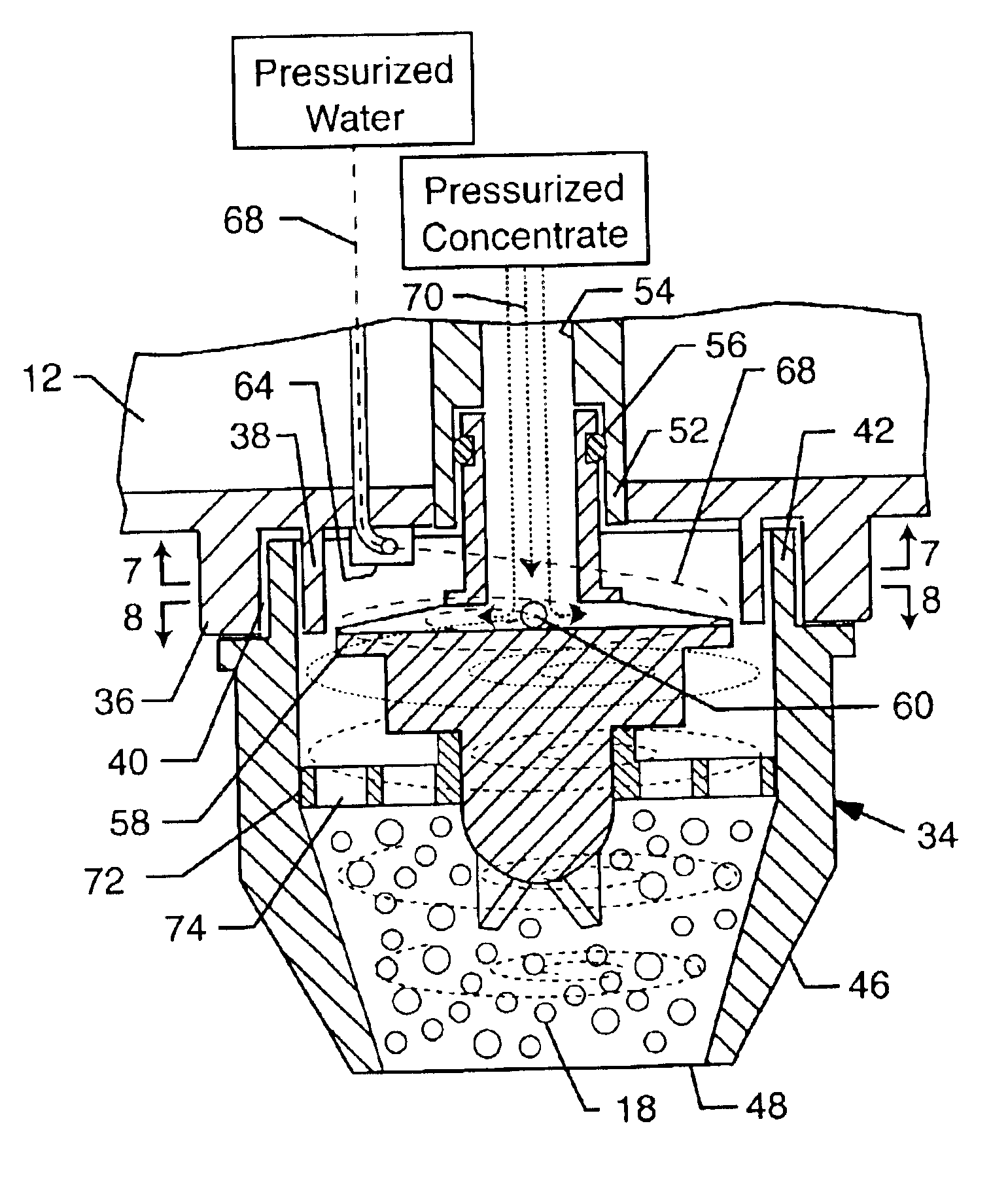
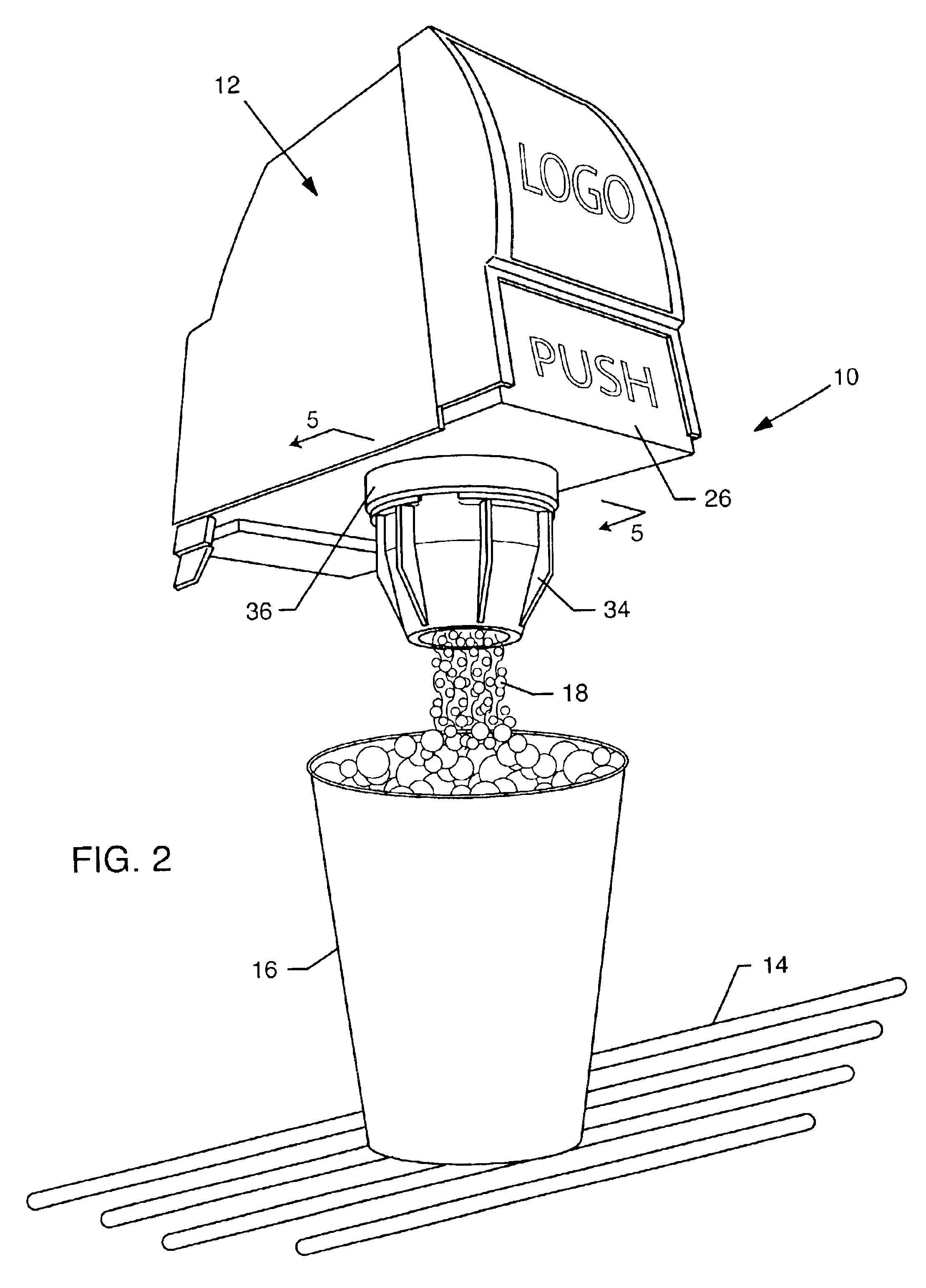
As shown in the accompanying drawings for purposes of illustration, the present invention resides in a post-mix beverage dispenser, generally referred to by the reference number 10, which uses conventional beverage dispenser heads and components which have been modified to create a frothed beverage in accordance with the present invention.

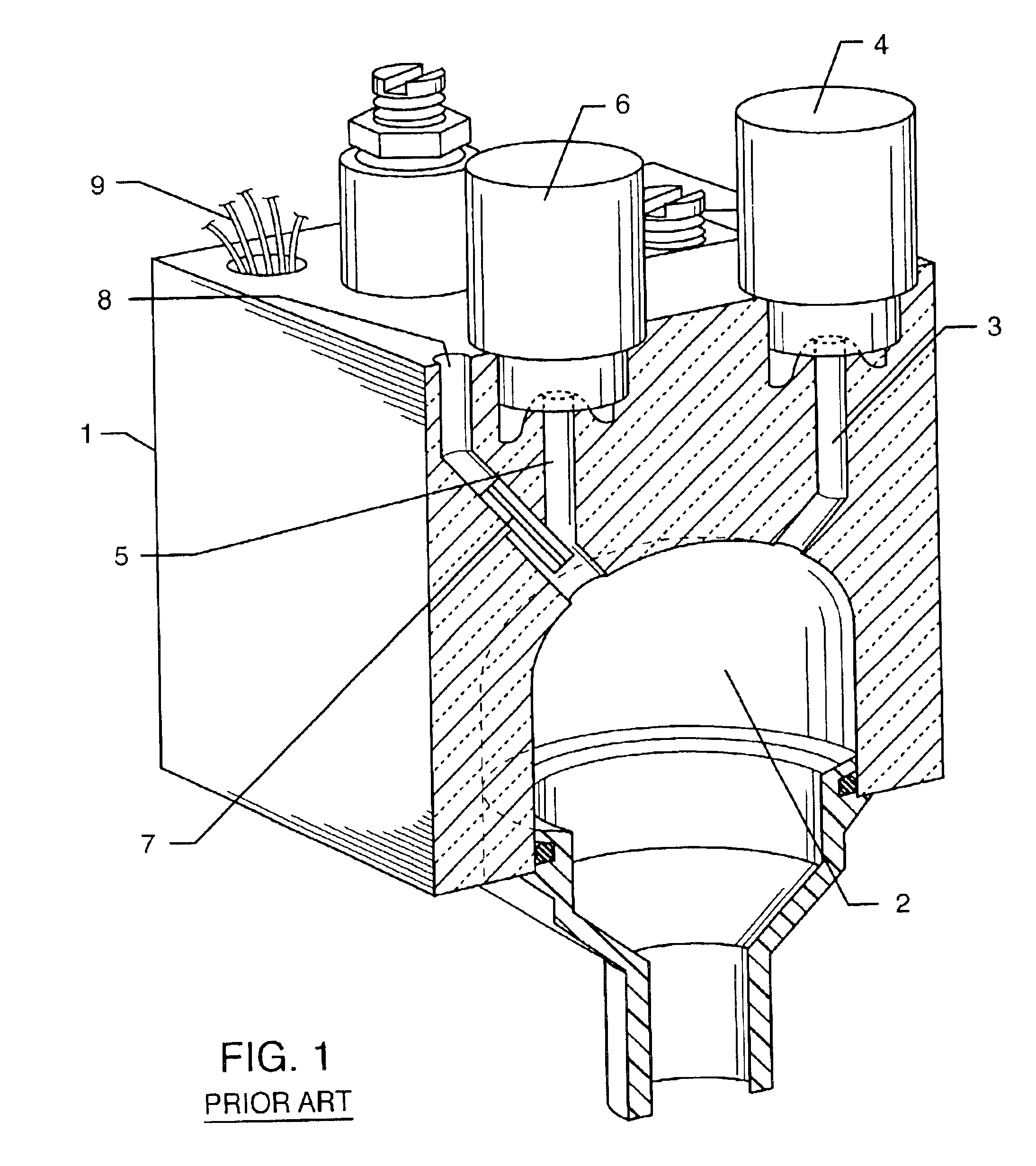
Referring now to FIGS. 1 and 2, a dispenser head 12 is shown which extends from a support structure (not shown) which, as is well-known in the art, can accommodate ice, fluid conduits to a source of water or other diluent, and beverage concentrates. Such support structures typically include a drain basin for collecting spilled beverage and ice, and having a grate 14 for supporting cups 16 thereon so that the cups 16 can be positioned below the dispenser head 12 to receive the frothed beverage 18.

With particular reference to FIG. 2, the dispenser head 12 includes a cover 20, shown in phantom, which houses the necessary components and conduits for di...


PUM


Abstract

A post-mix beverage dispenser includes a diluent jet directed at a wall of a mixing chamber thereof such that a swirling descending mass of diluent is formed. A concentrate dispensing outlet ejects concentrate into the swirling mass of diluent causing turbulent mixing of the diluent and the concentrate to create a frothed or whipped beverage. Instead of creating a swirling mass of diluent, the diluent jet and concentrate dispensing outlet may be oriented substantially directly at one another such that the streams of concentrate and diluent collide causing a turbulent mixing of the diluent and the concentrate.

Description

BACKGROUND OF THE INVENTIONThe present invention generally relates to beverage dispensers. More particularly, the present invention relates to a post-mix beverage dispenser for agitated or whipped beverages.There are presently a number of popular beverages sold in restaurants, snack shops, amusement parks, fast food outlets, and other establishments throughout the world. Some of these beverages are served in a whipped or foamed condition. That is, the beverage is agitated or whipped in the dispensing process to give the served beverage a foamy, froth texture. Typically, these beverages are made from a combination of a concentrate and a diluent, usually water. The concentrate by itself generally does not require refrigeration and has a shelf life of several months to over a year. However, when mixed with a diluent such as water or exposed to air, the combined beverage usually requires refrigeration to retard bacterial growth.For years, two basic type of fountain dispensers have been ...

Claims


Application Information

Patent Timeline
Patent Type & Authority Patents(United States)
IPC IPC(8): B67D1/00
CPCB67D1/0021B67D1/0085B67D1/0047B67D1/0044
Inventor FOX, DAVID
Owner FOX DAVID
Why Eureka
Try Eureka