

Child car seat
- Summary
- Abstract
- Description
- Claims
- Application Information
AI Technical Summary
Benefits of technology
Problems solved by technology
Method used
Image

Examples
first embodiment
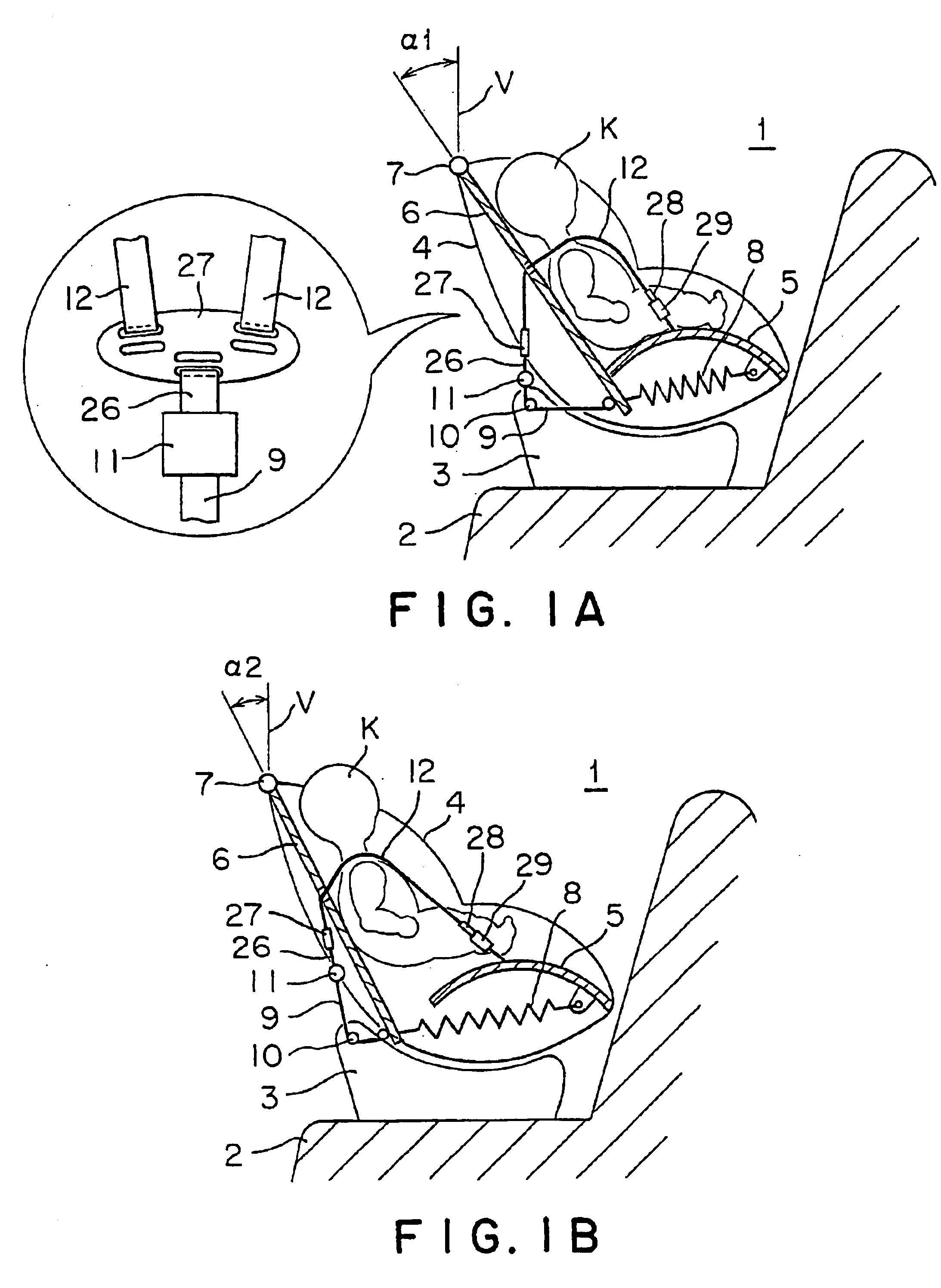
A first embodiment of the present invention is described in detail referring to FIGS. 1A and 1B.
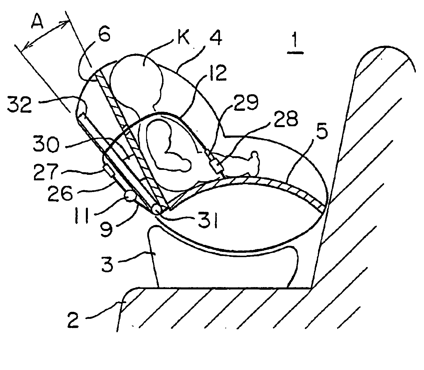
FIGS. 1A and 1B show the first embodiment of the present invention. In particular, FIG. 1A shows a child car seat 1 facing backward at a normal time, and FIG. 1B shows the child car seat facing backward at the time of impact.
The child car seat 1 for a child comprises a base 3, a child car seat body 4 mounted on the base 3, a seat portion 5 and a back portion 6 connected to the child car seat body 4. The child car seat 1 is mounted on a seat 2 of a vehicle facing forward, or facing backward as shown in FIGS. 1A and 1B. When the vehicle carries a child, the child car seat is often mounted facing backward as shown in the drawings.
As mentioned above, the seat portion is fixed on the child car seat body 4, while the top end of the back portion 6 is rotatably connected to the body 4 through a rotating shaft 7. Further, a spring member 8 is installed between the bottom end of the back portion 6 ...
second embodiment
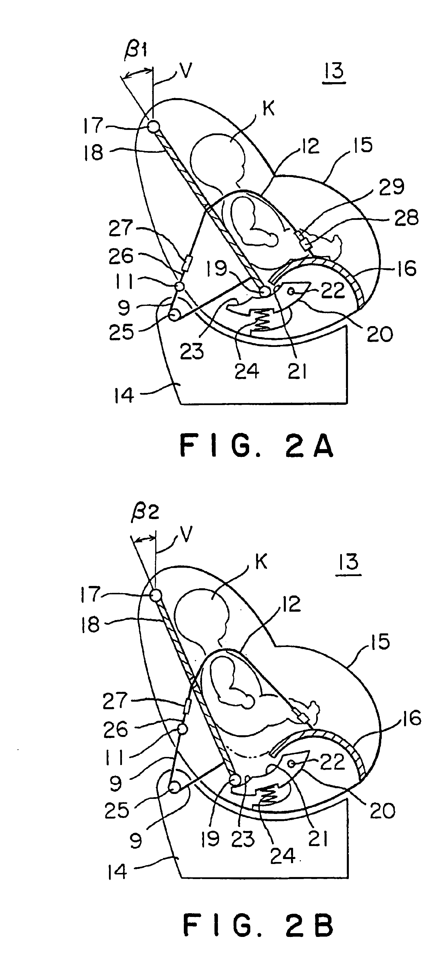
FIGS. 2A and 2B show a second embodiment of the invention. In particular, FIG. 2A shows a child car seat at a normal time, and FIG. 2B shows the same at an impact time.
In the second embodiment, a child car seat body 15 mounted on a base 14 of a child car seat 13 is provided with a fixing seat portion 16, and the top end of a back portion 18 is connected to the child car seat body 15 with a hinge through a rotating shaft 17. This is substantially the same as in the first embodiment. However, an elastic support structure of the bottom end of the back portion 18 is different from the first embodiment.
The bottom end of the back portion 18 is provided with a moving body 19 including a roller or a plastic slide body, and this moving body 19 is engaged with an elastic hooking device 20 attached to the child car seat body 15. The elastic hooking device 20 has a shape similar to a half moon, and an end of the hooking device is rotatably supported by the child car seat body 15 through a pin 2...
third embodiment
FIGS. 3A and 3B show a principle of a third embodiment, in particular FIG. 3A shows a child car seat at a normal time, and FIG. 3B shows the seat at a time of impact.
In the third embodiment, the child car seat is constructed so that a seat portion 5 and a back portion 6 are connected with a connecting member 40 made of a material to be broken at a connecting portion by impact force, and the back portion 6 and the seat portion are connected at the normal time. The connecting member 40 is broken and the seat portion 5 and the back portion 6 are disconnected by the impact force at the time of impact, and the back portion 6 rotates to move in a direction away from the seat portion 5.
In FIG. 3A, the top end of the back portion 6 is rotatably connected to a child car seat body 4 through a rotating shaft 7, and the bottom end of the back portion is connected to the seat portion 5 with the impact destructive connecting member 40 while an inclination angle of y between the back portion 6 and...
PUM
 Abstract
Description
Claims
Application Information