Spill-proof refrigerator shelf

Inactive Publication Date: 2005-03-29
MAYTAG
20 Cites 41 Cited by

AI-Extracted Technical Summary

Problems solved by technology

Gaps often exist between the panel and the frame members that allow liquid spilled on the panel to run off the refrigerator shelf through the gaps and spill onto other shelves and/or food items below.
Additionally, liquid spilled on the shelf may still seep into gaps between the frame and t...

Method used

In addition to having an easily cleaned, spill-proof surface as described above, shelf assembly 30 has the advantage of being simply constructed and relatively inexpensive to manufacture. As indicated above, frame member 110 is preferably molded of plastic. As is known in the art, pigments or dyes may be added during the molding process to produce a frame member 110 of a desired color. Shelf panel 102 is then placed onto frame member 110 such that peripheral edge portion 108 is spaced from side wall section 112 and cantilevered over bearing wall section 120. Adhesive 127 is then injected into channel 124 until flush with upper surface 104 of shelf panel 102. Adhesive 127 is preferably constituted by DOW RTV-739, but may be any other type of adhesive that provides a water or other fluid tight seal between shelf panel 102 and frame member 110. Planar support surface 121 of bearing wall section 120 directly contacts lower surface 106 of shelf panel 102 and aids in preventing uncured adhesive 127 from spilling out between bearing wall section 120 and lower surface 106 of shelf panel 102. Upon curing of adhesive 127, a hard, substantially continuous and easily cleaned...

Benefits of technology

In accordance with the most preferred form of the invention, the bearing wall portion of the frame member supports the shelf panel such that a peripheral edge portion of the shelf panel is cantilevered over the bearing wall section. The peripheral edge portion of the shelf panel and the side wall, bottom wall and bearing wall portions define a generally L-shaped channel in the frame member. An adhesive fills the channel and secures the shelf panel to the frame member in...

Abstract

A removable, spill-proof refrigerator shelf includes a glass shelf panel, a one-piece molded plastic frame member extending about the periphery of and supporting the glass shelf panel, and an adhesive injected into a channel created by the frame member for sealingly fixing the shelf panel within the frame member. The top of the adhesive is made flush with the top surface of the shelf panel, thereby forming a substantially continuous and easily cleaned surface. An integral outer rim is provided about the periphery of the frame member and acts as a barrier to prevent any liquid spilled on the shelf from flowing onto shelves and/or food below.

Application Domain

Technology Topic

Image

  • Spill-proof refrigerator shelf
  • Spill-proof refrigerator shelf
  • Spill-proof refrigerator shelf

Examples

  • Experimental program(1)

Example

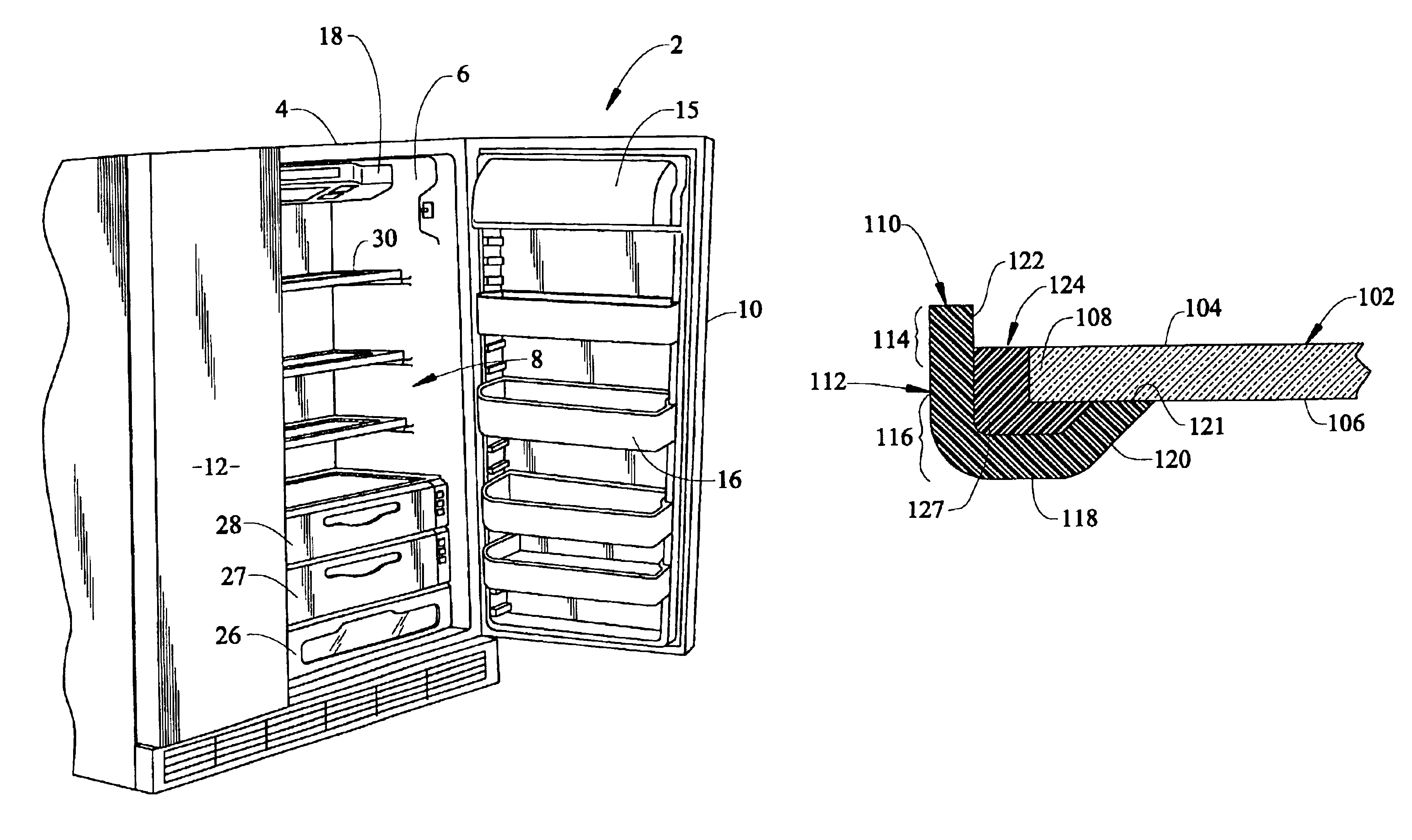
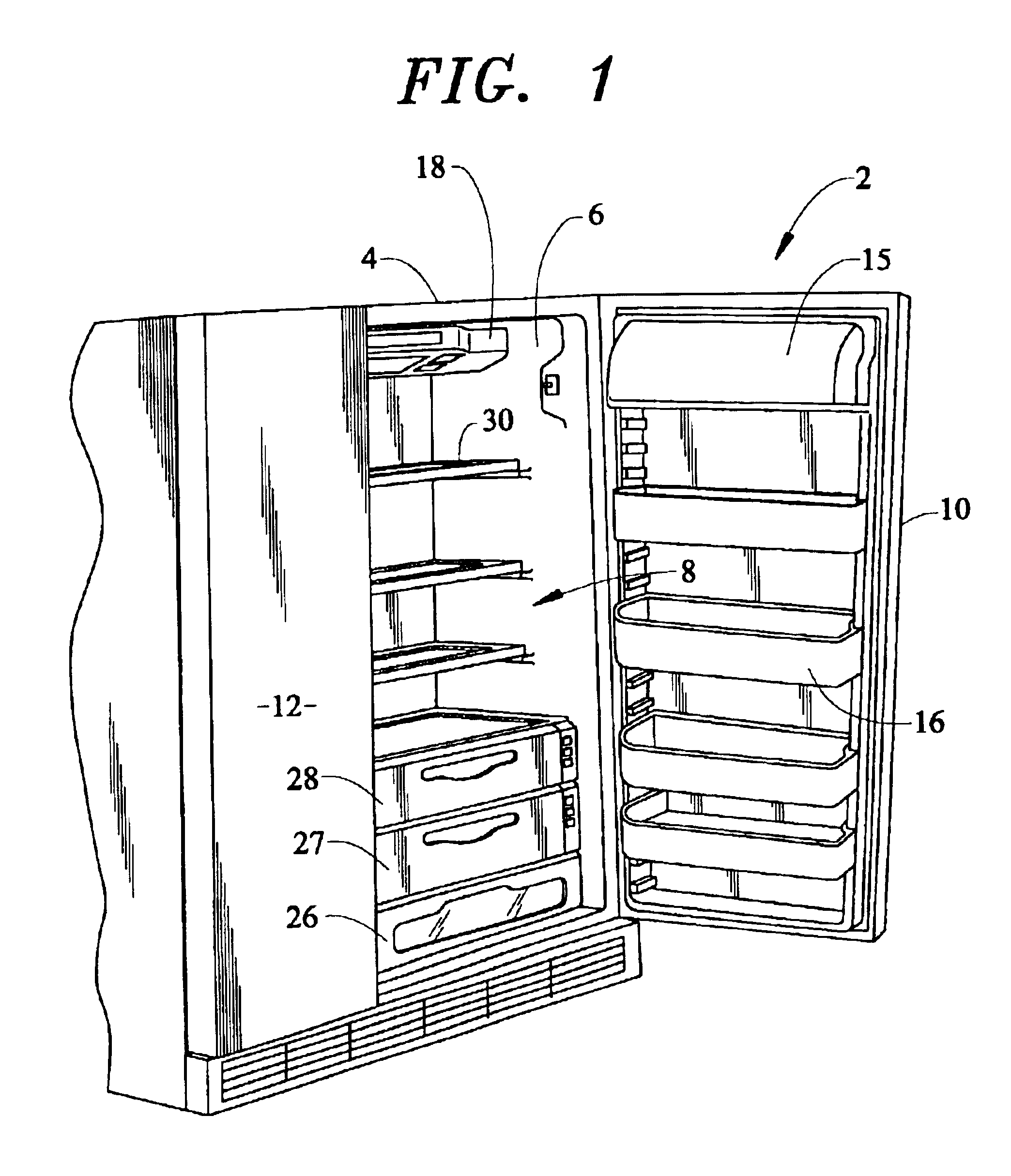
With initial reference to FIG. 1, a refrigerator cabinet 2 includes a shell 4 within which is positioned a liner 6 that defines a fresh food compartment 8. In a manner known in the art, fresh food compartment 8 can be accessed by the selective opening of a fresh food door 10. In a similar manner, a freezer door 12 can be opened to access a liner defined freezer compartment (not shown). For the sake of completeness, door 10 of refrigerator cabinet 2 is shown to include a dairy compartment 15 and various vertically adjustable shelving units, one of which is indicated at 16. Mounted in an upper region of fresh food compartment 8 is a temperature control housing 18 which, in a manner known in the art, can be used to regulate the temperature in both fresh food compartment 8 and the freezer compartment. At a lowermost portion of fresh food compartment 8 is illustrated various slidable bins, i.e., a lowermost bin 26 and higher, individually temperature controlled bins 27 and 28.
To this point, the above-described structure is known in the art and presented only for the sake of completeness. This structure is actually more fully described in U.S. Pat. No. 6,170,276 which is incorporated herein by reference. The present invention is actually directed to a removable, spill-proof shelf assembly generally indicated at 30. Although FIG. 1 illustrates three such shelf assemblies 30, it should be realized that the actual number of shelf assemblies can be readily varied.
Reference will now be made to FIGS. 2 and 3 in describing the preferred embodiment of spill-proof shelf assembly 30 of the present invention. As illustrated, shelf assembly 30 includes a preferably rectangular shelf panel 102 having upper and lower spaced surfaces 104 and 106, and a peripheral edge portion 108. Preferably, shelf panel 102 is constituted by a planar glass panel. Shelf assembly 30 also includes a frame member 110, preferably constituted by a single piece of plastic which is molded in a rectangular shape, with a substantially J-shaped cross-section. More specifically, frame member 110 includes a side wall section 112 having a top end portion 114 and a bottom end portion 116, a base wall section 118 formed integrally with and extending from the bottom end portion 116 of side wall section 112, and a bearing wall section 120. As shown, bearing wall section 120 is integrally formed with, and extends upwardly from, base wall section 118. Shelf panel 102 is supported on bearing wall section 120 such that peripheral edge portion 108 is cantilevered over bearing wall section 120 and spaced apart from side wall section 112. Preferably, bearing wall section 120 defines a planar support surface 121 on which the lower surface 106 of shelf panel 102 is supported. The top end portion 114 of side wall section 112 projects above upper surface 104 of shelf panel 102 and defines a rim 122 about the periphery of spill-proof shelf assembly 30.
Peripheral edge portion 108, side wall section 112, lower surface 106 of shelf panel 102, base wall section 118 and bearing wall section 120 collectively define a channel 124 which is filled with an adhesive 127. Adhesive 127 secures peripheral edge portion 108 of shelf panel 102 to frame member 110 in a fluid tight manner. In the most preferred embodiment of the invention, bearing wall section 120 is arranged at an obtuse angle with respect to base wall section 118, thus advantageously establishing a larger surface area upon which lower surface 106 rests. The cantilevered arrangement of peripheral edge portion 108 actually defines an undercut zone (not separately labeled) into which adhesive 127 extends. Therefore, channel 124 is generally L-shaped in cross-section. In any event, adhesive 127 fixes shelf panel 102 to frame member 110. Most preferably, the top of adhesive 127 is established flush with upper surface 104 of shelf panel 102, thereby providing a continuous and easily cleaned shelf surface. With this arrangement, any small amount of liquid spilled on upper surface 106 of shelf assembly 30 will be contained thereon by rim 122.
In addition to having an easily cleaned, spill-proof surface as described above, shelf assembly 30 has the advantage of being simply constructed and relatively inexpensive to manufacture. As indicated above, frame member 110 is preferably molded of plastic. As is known in the art, pigments or dyes may be added during the molding process to produce a frame member 110 of a desired color. Shelf panel 102 is then placed onto frame member 110 such that peripheral edge portion 108 is spaced from side wall section 112 and cantilevered over bearing wall section 120. Adhesive 127 is then injected into channel 124 until flush with upper surface 104 of shelf panel 102. Adhesive 127 is preferably constituted by DOW RTV-739, but may be any other type of adhesive that provides a water or other fluid tight seal between shelf panel 102 and frame member 110. Planar support surface 121 of bearing wall section 120 directly contacts lower surface 106 of shelf panel 102 and aids in preventing uncured adhesive 127 from spilling out between bearing wall section 120 and lower surface 106 of shelf panel 102. Upon curing of adhesive 127, a hard, substantially continuous and easily cleaned shelf surface is produced.
Although described with reference to a preferred embodiment of the invention, it should be readily understood that various changes and/or modifications can be made to the invention without departing from the spirit thereof. For instance, at the time of manufacturing, recesses, projections, rails, or the like, associated with supporting removable shelf assembly 30 in the refrigerator cabinet 2, may be integrally molded into frame member 110. In general, the invention is only intended to be limited by the scope of the following claims.

PUM

no PUM

Description & Claims & Application Information

We can also present the details of the Description, Claims and Application information to help users get a comprehensive understanding of the technical details of the patent, such as background art, summary of invention, brief description of drawings, description of embodiments, and other original content. On the other hand, users can also determine the specific scope of protection of the technology through the list of claims; as well as understand the changes in the life cycle of the technology with the presentation of the patent timeline. Login to view more.

Similar technology patents

Chemical cleaning agent for clearing impurities such as ferrous sulfide

InactiveCN102345136AEasy to cleanPrevent spontaneous combustionNon toxicitySODIUM DODECYL BENZENE SULFONATE
Owner:NINGBO ZHONGYI PETROCHEM TECH

Domestic ultrasonic washer

InactiveCN101536894AImprove cleaning efficiencyEasy to cleanTableware washing/rinsing machinesSpray nozzlePiping
Owner:苏伟民

Classification and recommendation of technical efficacy words

Why Eureka
Try Eureka