Bearing material for porous hydrostatic gas bearing and porous hydrostatic gas bearing using the same
a technology of hydrostatic gas bearing and porous hydrostatic gas, which is applied in the direction of bearings, shafts and bearings, mechanical equipment, etc., can solve the problems of affecting the gas permeability of the surface of the bearing, the number of problems to be overcome, and the surface is subjected to machining in many cases, so as to increase the amount of flotation and enhance the porosity of the porous sintered metal layer
- Summary
- Abstract
- Description
- Claims
- Application Information
AI Technical Summary
Benefits of technology
Problems solved by technology
Method used
Image

Examples
example 1
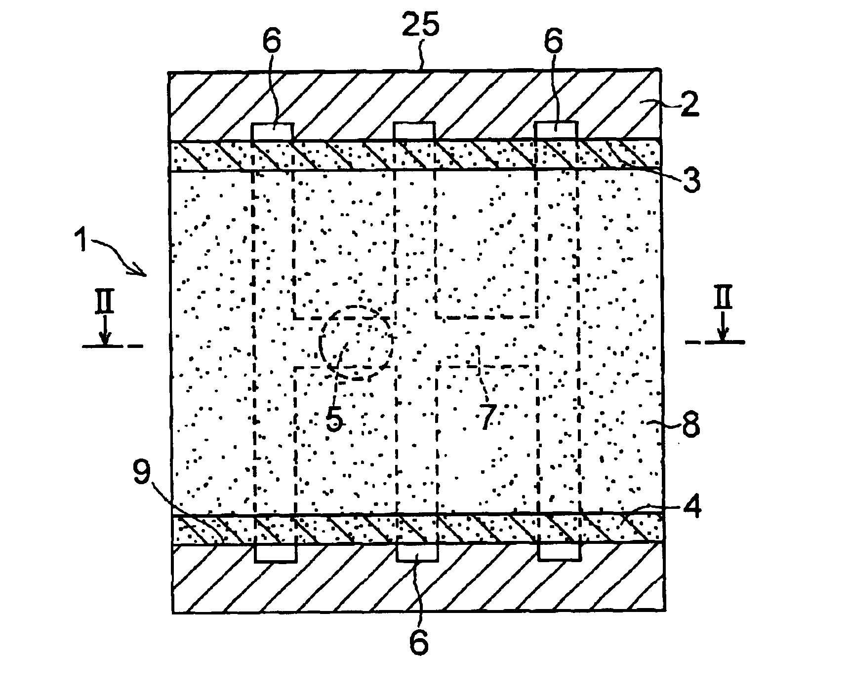
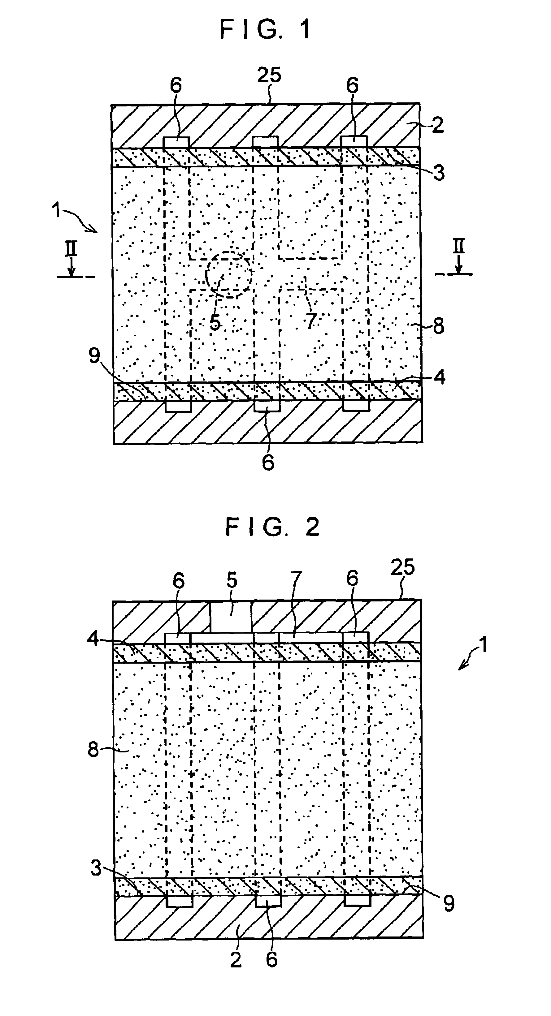
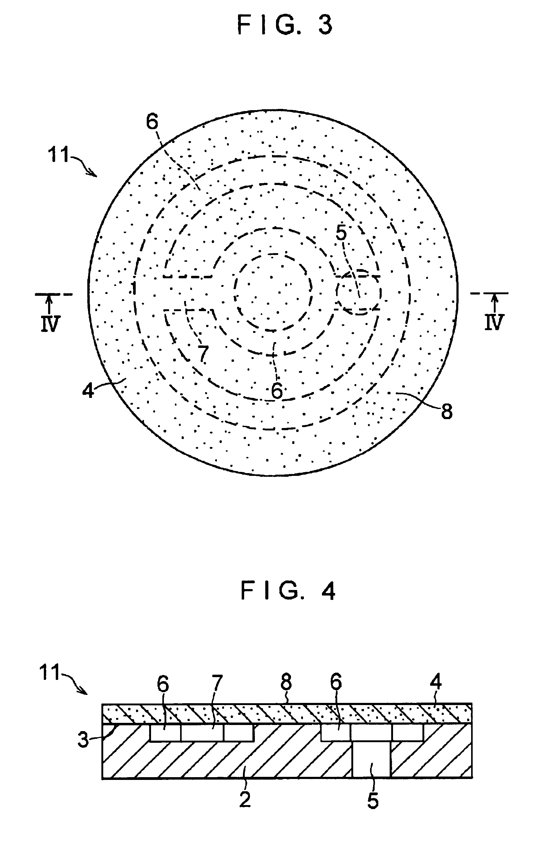
The hollow cylindrical backing metal 2 made of a martensitic stainless steel [SUS 420 J 2 (B)] having an inside diameter of 30 mm, an outside diameter of 45 mm, and a length of 30 mm was prepared. Three annular grooves 6 having a width of 2 mm and a depth of 2 mm and arranged at equal intervals along the axial direction of the backing metal 2, as well as one groove 7 for allowing the annular grooves 6 to communicate with each other and extending along the axial direction of the backing metal 2, were respectively formed in the inner surface 9 of this hollow cylindrical backing metal 2. Additionally, one hole 5 which was open to the groove 7 from the outer surface 25 of the backing metal 2 was formed.
A 3 μm-thick nickel plated layer was formed on that inner surface 9 of the hollow cylindrical backing metal 2 with the annular grooves 6, the groove 7, and the hole 5 formed therein which excludes the surface portions of the annular grooves 6, the groove 7, and the hole 5. A 10 μm-thick c...
example 2
In the same way as Example 1, the hollow cylindrical backing metal 2 was prepared which was provided with the annular grooves 6, the groove 7, and the hole 5 and was provided with two plated layers including a 3 μm-thick nickel plated layer formed on the inner surface 9 excluding the surface portions of the annular grooves 6, the groove 7, and the hole 5, as well as a 15 μm-thick copper plated layer formed on the surface of the nickel plated layer.
A mixed powder (copper: 58.71 wt. %; tin: 8 wt. %; nickel: 28 wt. %; phosphorus: 0.29 wt. %; and graphite: 5 wt. %) was prepared by mixing the following components in a V-type mixer for 5 minutes: 8% by weight of an atomized tin powder passing through a 250-mesh sieve, 28% by weight of an electrolytic nickel powder passing through a 250-mesh sieve, 2.0% by weight of a copper-phosphorus (phosphorus: 14.5%) powder passing through a 120-mesh sieve, 5% by weight of a graphite powder (particles of an inorganic substance) passing through a 150-m...
example 3
In the same way as Example 1, the hollow cylindrical backing metal 2 was prepared which was provided with the annular grooves 6, the groove 7, and the hole 5 and was provided with the two plated layers including a 10 μm-thick nickel plated layer formed on the inner surface 9 excluding the surface portions of the annular grooves 6, the groove 7, and the hole 5, as well as a 20 μm-thick copper plated layer formed on the surface of the nickel plated layer.
A mixed powder (copper: 58.58 wt. %; tin: 8 wt. %; nickel: 28 wt. %; phosphorus: 0.42 wt. %; and graphite: 5 wt. %) was prepared by mixing the following components in a V-type mixer for 5 minutes: 8% by weight of an atomized tin powder passing through a 250-mesh sieve, 28% by weight of an electrolytic nickel powder passing through a 250-mesh sieve, 3.0% by weight of a copper-phosphorus (phosphorus: 14.5%) powder passing through a 120-mesh sieve, 5% by weight of a graphite powder (particles of an inorganic substance) passing through a ...
PUM
| Property | Measurement | Unit |
|---|---|---|
| Percent by mass | aaaaa | aaaaa |
| Percent by mass | aaaaa | aaaaa |
| Percent by mass | aaaaa | aaaaa |
Abstract
Description
Claims
Application Information
 - R&D
- Intellectual Property
- Life Sciences
- Materials
- Tech Scout
- Unparalleled Data Quality
- Higher Quality Content
- 60% Fewer Hallucinations
Browse by: Latest US Patents, China's latest patents, Technical Efficacy Thesaurus, Application Domain, Technology Topic, Popular Technical Reports.
© 2025 PatSnap. All rights reserved.Legal|Privacy policy|Modern Slavery Act Transparency Statement|Sitemap|About US| Contact US: help@patsnap.com