
Radio network performance management

Inactive Publication Date: 2005-03-29
CARRIERCOMM
View PDF4 Cites 47 Cited by
  • Summary
  • Abstract
  • Description
  • Claims
  • Application Information

AI Technical Summary

Benefits of technology

The requested results may show performance of a single link, s

Problems solved by technology

Such management systems are effective in dealing with systems where problems are mainly basic equipment faults, but they are not effective in dealing with problems that are more complex than a simple equipment failure.
In radio systems, many operational conditions are transient in nature, such as weather-related, propagation, and mutual interference communication problems.
However, such a link will have more degradation during the increase of propagation attenuation than otherwise, and thus may experience undesirable results only upon occurrence of increased propagation attenuation.
Trouble shooting of transient network conditions is extremely difficult because the environmental conditions that create the problem do not exist all the time.
An additional problem occurs when an area is so densely populated with radio links that transmissions from one link are detected by, and interfere with, another link.
Side-lobe propagation can interfere with radio receivers that are not supposed to be in the transmit path.
Similarly, an antenna that becomes slightly misaligned may inadvertently point to an unrelated transmitter or receiver.
Problems such as these do not involve equipment failures that can be quickly detected, and the equipment that is causing the problem is frequently not the equipment that shows degraded performance.
Managing the operation and performance of radio networks involves two problems which are not addressed by conventional Parameter monitoring standards.
The second, more complex, problem is how to measure the right data at the right time in order to properly assess link conditions.
So if the receive power is measured continuously, then 90% of data does not yield useful information.
If a continuous rate is high enough to nearly instantaneously catch the onset of rain and any change in density thereafter, then the total amount of data may not be manageable.

Method used


Image

  • Radio network performance management
  • Radio network performance management
  • Radio network performance management

Examples


Embodiment Construction

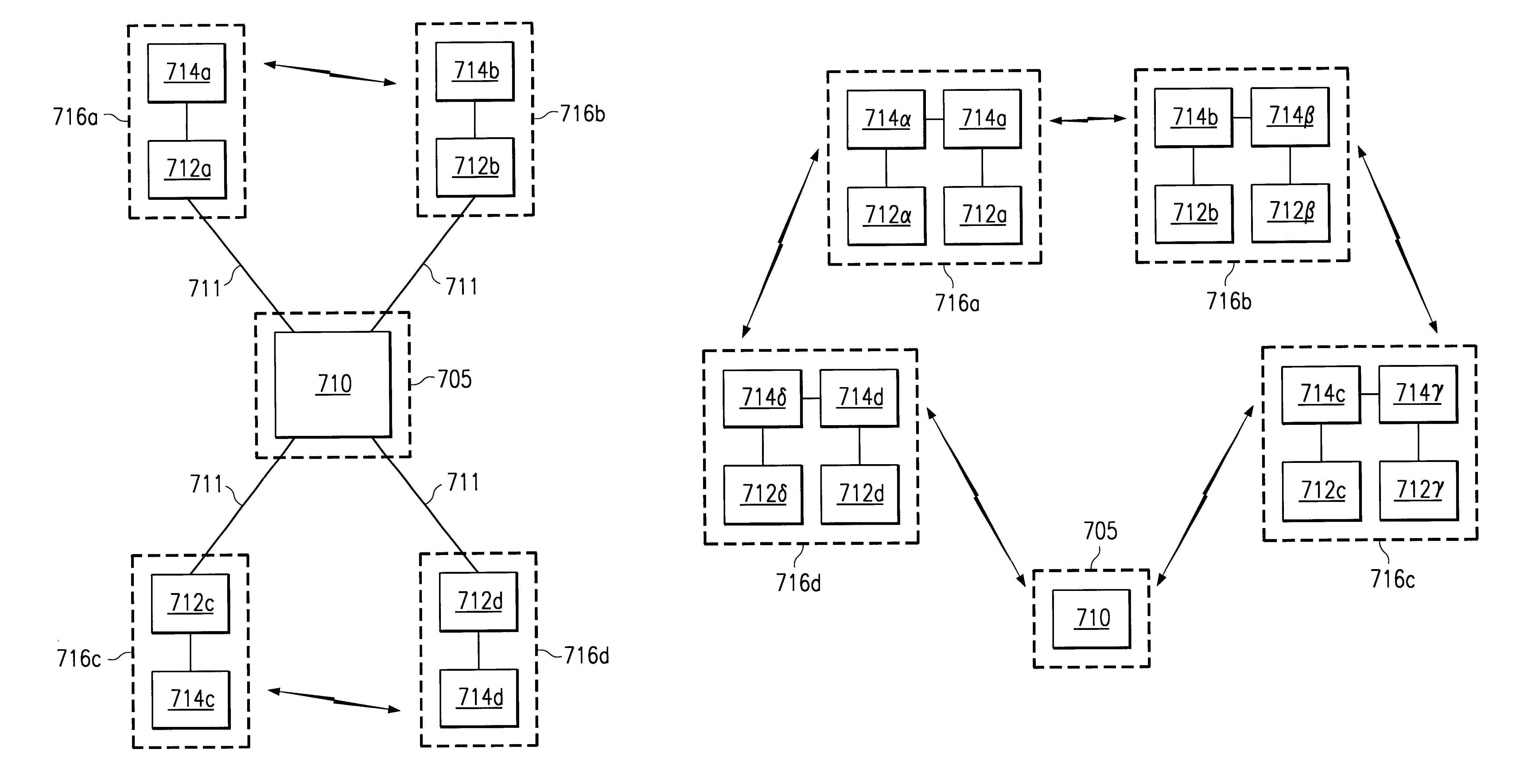
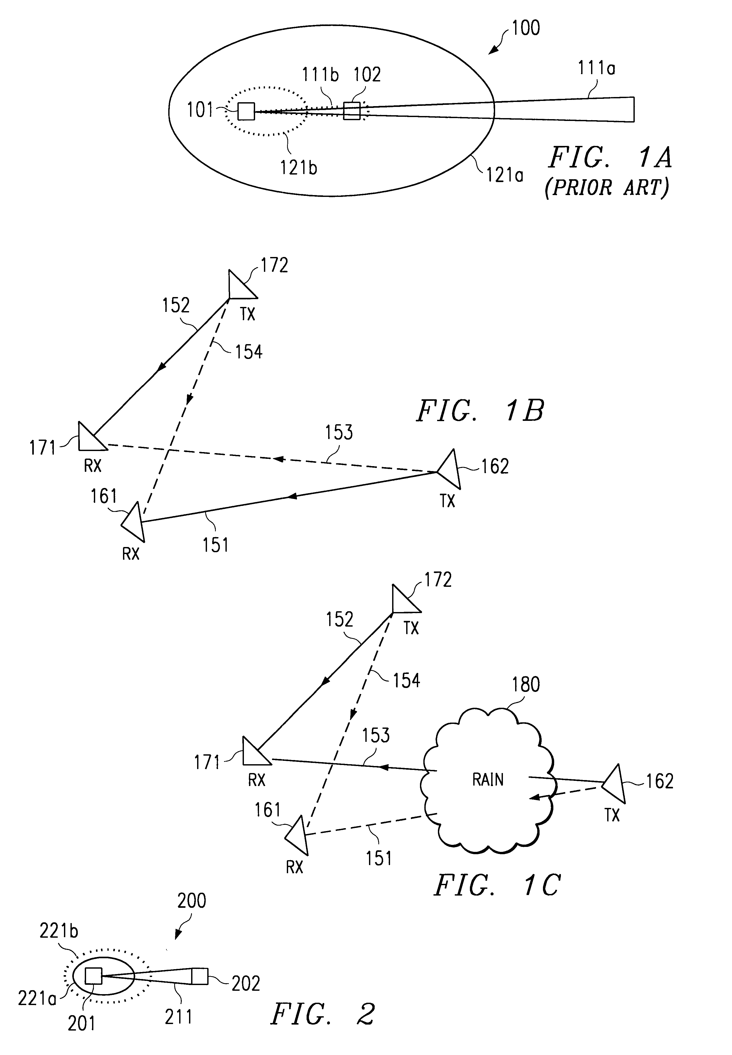
In a typical point-to-point communication system communication links are established between a transmitter and receiver pair in order to carry signals and information there between. For example, directing attention to FIG. 1A wherein a prior art point-to-point communication link is shown generally as system 100, transmitter 101 and receiver 102 form a transmitter / receiver pair. Here transmitter 101 has main beam 111a directed toward receiver 102 in order to establish a wireless communication link suitable for providing signals and information there between. Transmitter 101 also includes area of influence 121a, which may consist of side lobes, back lobes, and the like, wherein signals radiated by transmitter 101 may be received outside of main beam 111a.

Accordingly, any receiver disposed within either main beam 111a or area of influence 121a may establish communication with transmitter 101. However, in a point-to-point system, it is typically desired that only a single receiver esta...


PUM


Abstract

A system and method for testing a radio network. A user at a central site may choose specific radios to be tested and specific test parameters for each one. The user may specify start and stop times, sample rates, whether one or multiple links are to be simultaneously tested, whether results should be presented as snap shots, statistical tables / graphs / charts, or as correlated data from multiple links. Distributed testing is permitted, in which the operational characteristics of one radio are varied, and another radio is monitored for a corresponding change. Once data has been gathered from one or more tests on one or more links, the data may be returned to the central site for analysis and presentation to the user in the selected format.

Description

TECHNICAL FIELDThe invention relates to the field of management in a network of radios providing data communication through a plurality of interconnected links. More particularly, it relates to specifying, collecting and communicating relevant data involving the operation and performance of a radio-based network.BACKGROUNDLarge networks may contain many pieces of equipment and communication links distributed over a large geographic area, all of which must operate together in an integrated manner. Such networks not only need a network management system, but network management system generally benefit from remote or centralized control capability. A good example of this capability is the industry standard of Transmission Management Network ((TMN) that defines the function of network system operation, alarm, maintenance and provisioning (Parameter monitoring ). This industry standard was used in support of the development of the Synchronous Optical Network transmission system (SONET).S...

Claims


Application Information

Patent Timeline
IPC IPC(8): H04L12/26H04L12/56
CPCH04W24/00H04W12/10
Inventor CHOW, PETER EL KWANKRIZMAN, KEVIN J.
Owner CARRIERCOMM
Learn More