Drive-force distribution controller and drive-force distribution method for four-wheel-drive vehicle

a technology of drive-force distribution controller and drive-force distribution method, which is applied in the direction of process control, instruments, machine control, etc., can solve the problems of excessive command torque, inability of conventional drive-force distribution controller to effect drive-force distribution in accordance with traveling conditions, and inability to properly control the torque transmitted to the front or rear wheels during cornering. to achieve the effect of improving both steerability and motion stability of the vehicl

Inactive Publication Date: 2005-03-29
TOYODA MASCH WORKS LTD
View PDF13 Cites 16 Cited by
  • Summary
  • Abstract
  • Description
  • Claims
  • Application Information

AI Technical Summary

Benefits of technology

In view of the foregoing, an object of the present invention is to provide a drive-force distribution controller and drive-force distribution method for a four-wheel-drive vehicle, which can improve both steerablity and motion stability of a vehicle.
Still another object of the present invention is to provide a drive-force distribution controller and drive-force distribution method for a four-wheel-drive vehicle, which can improve the steerability and motion stability of a vehicle and can reduce shock and noise generated upon clutch engagement.

Problems solved by technology

However, the conventional drive-force distribution controller cannot properly control the torque transmitted to the front or rear wheels during cornering.
In such a state, if the torque value obtained from the differential-rotational-speed-to-torque map deviates from a proper range or intended range (i.e., the torque value becomes excessive large because of large differential rotational speed and high vehicle speed), the steering characteristics tend to shift to the under-steer side, and the entire vehicle body may be pushed outward from an intended cornering path.
However, the conventional drive-force distribution controller involves the following problems.
Therefore, in the case where the throttle opening increases abruptly in a low speed range, such as the case of abrupt starting, the command torque becomes excessively large, and in some cases, a driver feels a shock produced upon engagement operation of the electromagnetic clutch.
Therefore, in some cases, the conventional drive-force distribution controller fails to effect drive force distribution in accordance with traveling conditions.
However, the conventional drive-force distribution controller involves the following problems.
Accordingly, during low-speed travel, shock or noise may be generated upon engagement of the clutch, and the motion stability of the vehicle may be impaired.
Further, during intermediate or high-speed travel, under-steer may become strong, or under-steer may occur suddenly, with the result that the steerability and stability of the vehicle may be impaired.

Method used


Image

  • Drive-force distribution controller and drive-force distribution method for four-wheel-drive vehicle
  • Drive-force distribution controller and drive-force distribution method for four-wheel-drive vehicle
  • Drive-force distribution controller and drive-force distribution method for four-wheel-drive vehicle

Examples


first embodiment

<Overall Structure>

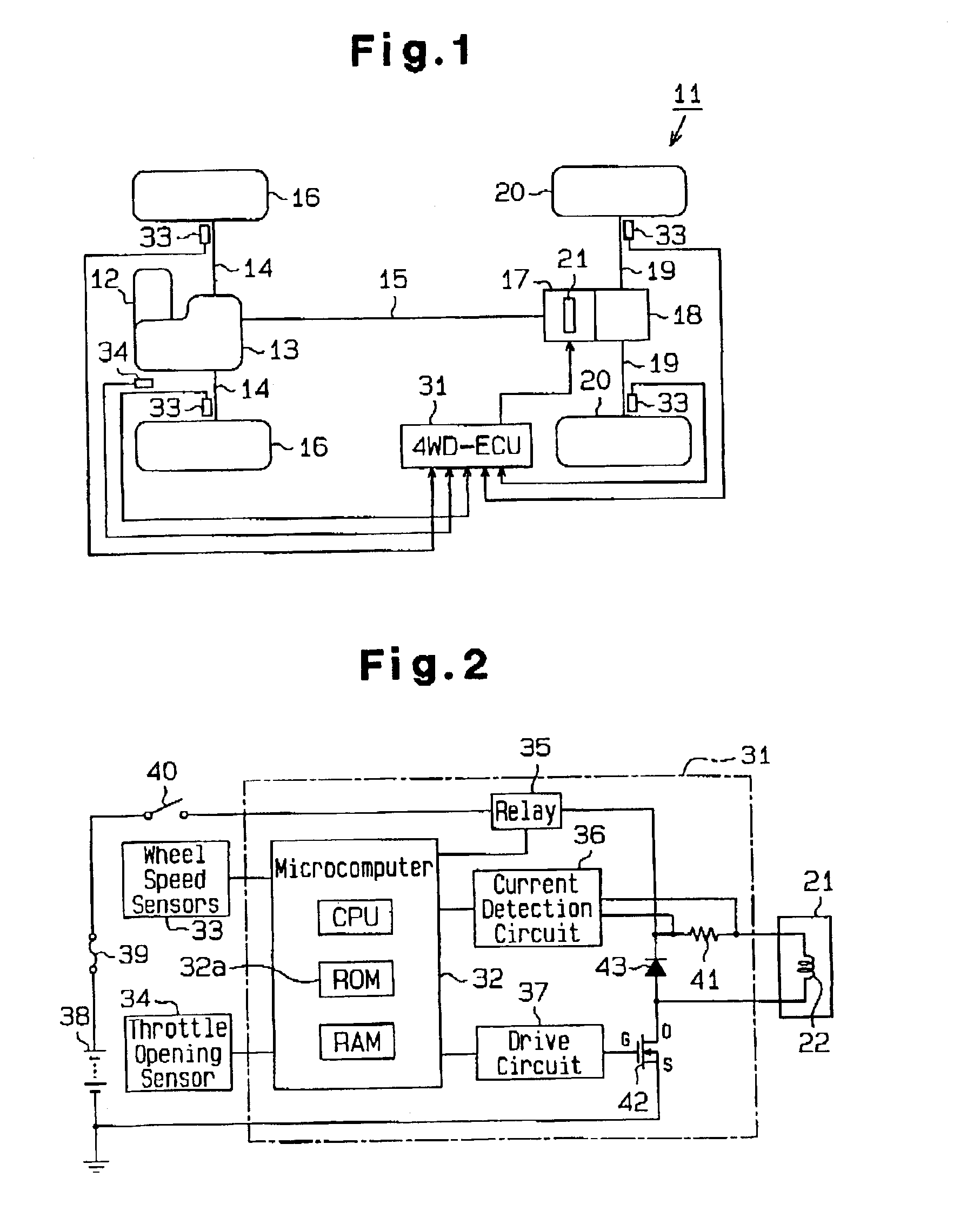
As shown in FIG. 1, a four-wheel-drive vehicle 11 includes an internal combustion engine 12 and a transaxle 13. The transaxle 13 includes a transmission, a transfer, and other necessary components. A pair of front axles 14 and a drive shaft 15 are connected to the transaxle 13. Front wheels 16 are connected to the front axles 14. A drive-force transmission apparatus (coupling) 17 is connected to the drive shaft 15. A rear differential 18 is connected to the drive-force transmission apparatus 17 via an unillustrated drive-pinion shaft. Rear wheels 20 are connected to the rear differential 18 via a pair of rear axles 19.

Driving force or torque output from the engine 12 is transmitted to the front wheels 16 via the transaxle 13 and the front axles 14. When the drive shaft 15 and the drive pinion shaft are coupled to each other by means of the drive-force transmission apparatus 17, the torque output from the engine 12 is transmitted to the rear wheels 20 via the ...

second embodiment

The overall structure of the four-wheel-drive vehicle, the structure of the drive-force transmission apparatus, and the electrical configuration are identical with those in the first embodiment, and therefore their repeated descriptions are omitted.

<Operation of the Second Embodiment>

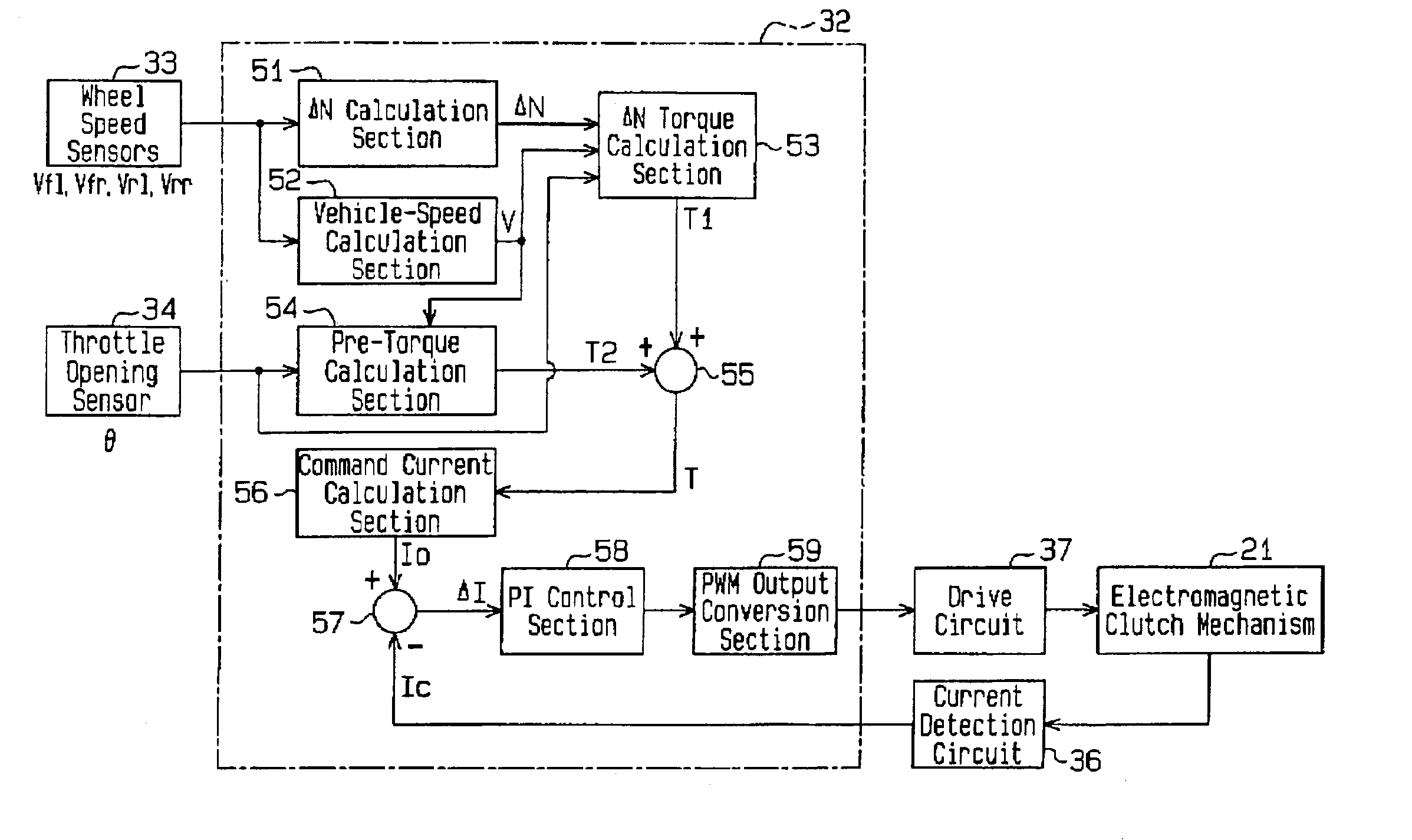
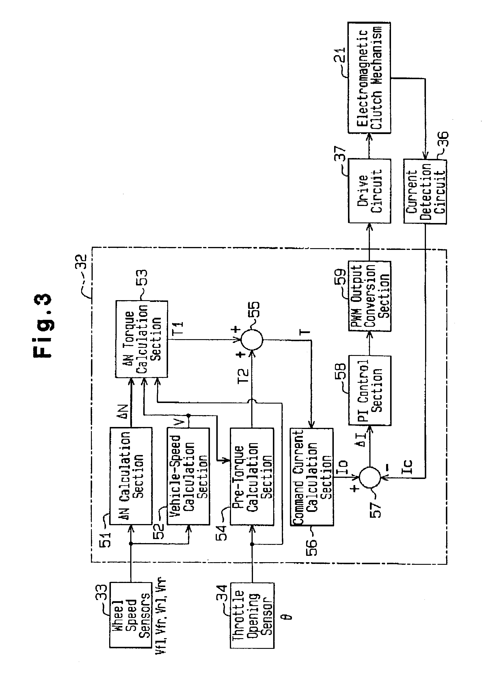
Various functions of the microcomputer 32 which are realized through execution of the various control programs stored in the ROM 32a will be described with reference to the functional block diagram shown in FIG. 3. Notably, various parameters, such as wheel speeds Vfl, Vfr, Vrl, Vrr, throttle opening θ, and differential rotational speed ΔN, refer to corresponding signals.

The microcomputer 32 performs drive-force distribution control as follows. The wheel speeds Vfl, Vfr, Vrl, and Vrr of the left and right front wheels and the left and right rear wheels detected by the wheel speed sensors 33 are fed to a differential-rotational-speed calculation section (hereinafter referred to as the “ΔN calculatio...

third embodiment

The overall structure of the four-wheel-drive vehicle, the structure of the drive-force transmission apparatus, and the electrical configuration are identical with those in the first embodiment, and therefore, their repeated descriptions are omitted.

<Operation of the Third Embodiment>

Next, various functions of the microcomputer 32 which are realized through execution of the various control programs stored in the ROM 32a will be described with reference to the functional block diagram shown in FIG. 10. Notably, various parameters, such as wheel speeds Vfl, Vfr, Vrl, Vrr, throttle opening θ, and differential rotational speed ΔN, refer to corresponding signals.

The microcomputer 32 performs drive-force distribution control as follows. The wheel speeds Vfl, Vfr, Vrl, and Vrr of the left and right front wheels 16 and the left and right rear wheels 20 detected by the wheel speed sensors 33 are fed to a differential-rotational-speed calculation section (hereinafter referred to as the “...


PUM


Abstract

A drive-force distribution controller controls a drive-force transmission apparatus of a vehicle in order to control transmission of drive force to rear wheels or front wheels of the vehicle in accordance with a designated drive-force transmission ratio. The drive-force transmission ratio is changed on the basis of vehicle speed, differential rotational speed (speed difference between the front and rear wheels), and throttle opening. Alternatively, the drive-force transmission ratio is changed on the basis of vehicle speed, throttle opening, and throttle open speed. The change speed of current which is supplied to the drive-force transmission apparatus in order to control the drive-force transmission ratio is adjusted in accordance with a command current filter value which is determined on the basis of vehicle speed and a command current filter map of a vehicle-speed responsive type.

Description

BACKGROUND OF THE INVENTION1. Field of the InventionThe present invention relates to a drive-force distribution controller and a drive-force distribution method for a four-wheel-drive vehicle.2. Description of the Related ArtConventionally, there has been known a drive-force distribution controller for a four-wheel-drive vehicle which variably controls the drive-force transmission ratio of a drive-force transmission apparatus in accordance with difference in rotational speed between front and rear wheels (differential rotational speed) and vehicle speed. Specifically, the drive-force distribution controller determines a drive force or torque corresponding to a differential rotational speed and a vehicle speed with reference to a differential-rotational-speed-to-torque map, and controls the engagement force of an electromagnetic clutch of the drive-force transmission apparatus so that the determined torque is transmitted to the front wheels or the rear wheels. The differential-rotati...

Claims


Application Information

Patent Timeline
Patent Type & Authority Patents(United States)
IPC IPC(8): B60K17/35B60K23/08F16D48/12
CPCB60K17/35B60K23/0808Y10T477/606B60W2520/28B60W2510/0604
Inventor MAEKAWA, AKIOSHIGETA, RYOHEI
Owner TOYODA MASCH WORKS LTD
Why Eureka
Try Eureka