
Grass trimmer drivable by power tool

a power tool and trimmer technology, applied in the field of grass trimmers, can solve the problems of large volume of typical grass trimmers, high cost for users, and the inability of typical power tools to rotate or drive the typical grass trimmers

Inactive Publication Date: 2005-04-05
YANG CHUNG JENG
View PDF9 Cites 23 Cited by
  • Summary
  • Abstract
  • Description
  • Claims
  • Application Information

AI Technical Summary

Benefits of technology

In accordance with one aspect of the invention, there is provided a grass trimmer comprising a housing, a fixed cutter device secured to the housing, and including at least one stationary cutter blade extended out of the housing, a movable cutter device rotatably secured to the fixed cutter device with a pivot shaft and rotatable relative to the fixed cutter device in reciprocating action, the movable cutter device including at least one cutter blade extended out of the housing, and movable relative to the stationary cutter blade of the fixed cutter device for conducting cutting operations, a rotary member rotatably attached to the housing and including an eccentric member extended therefrom and engageable with the movable cutter device, to cause the movable cutter device to move relative to the fixed cutter device in reciprocating action when the rotary member is rotated relative to the housing, a drive shank secured to the rotary member and rotated in concert with the rotary member and including a free end extended out of the housing, and a power tool including an engaging end attachable to the free end of the shank, to rotate and drive the rotary member relative to the housing, and to move the eccentric member relative to the movable cutter device, and to move the movable cutter device relative to the fixed cutter device in reciprocating action.

Problems solved by technology

For example, U.S. Pat. No. 3,973,378 to Bartasevich et al. and U.S. Pat. No. 5,197,268 to Barrera disclose two of the typical grass trimmers each also comprising a motor solidly attached to or secured to a housing, for rotating or driving cutter blades, such that the typical grass trimmers may comprise a large volume and may be expensive for the users.
In addition, the typical power tools may not be used to rotate or drive the typical grass trimmers.

Method used


Image

  • Grass trimmer drivable by power tool
  • Grass trimmer drivable by power tool
  • Grass trimmer drivable by power tool

Examples


Embodiment Construction

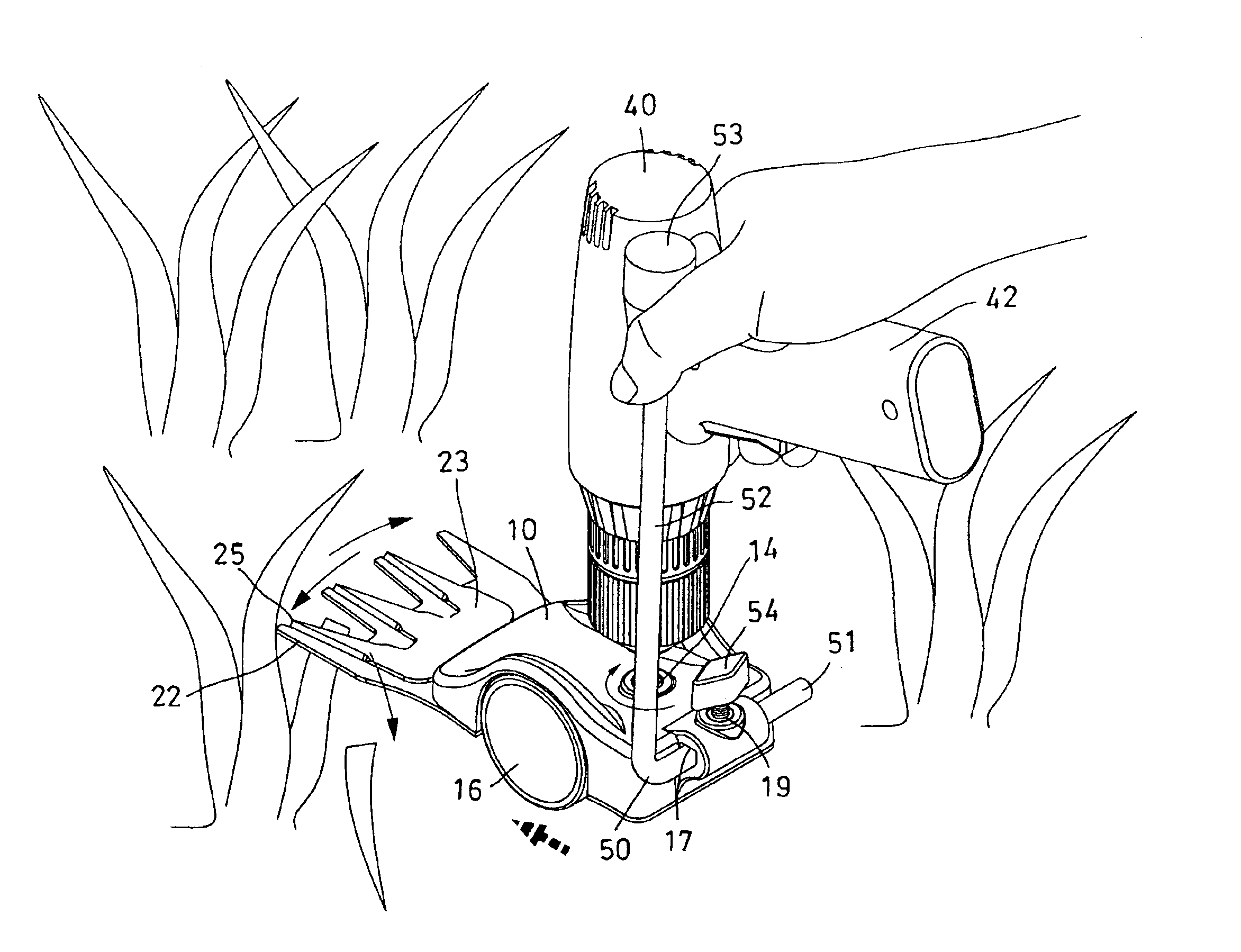
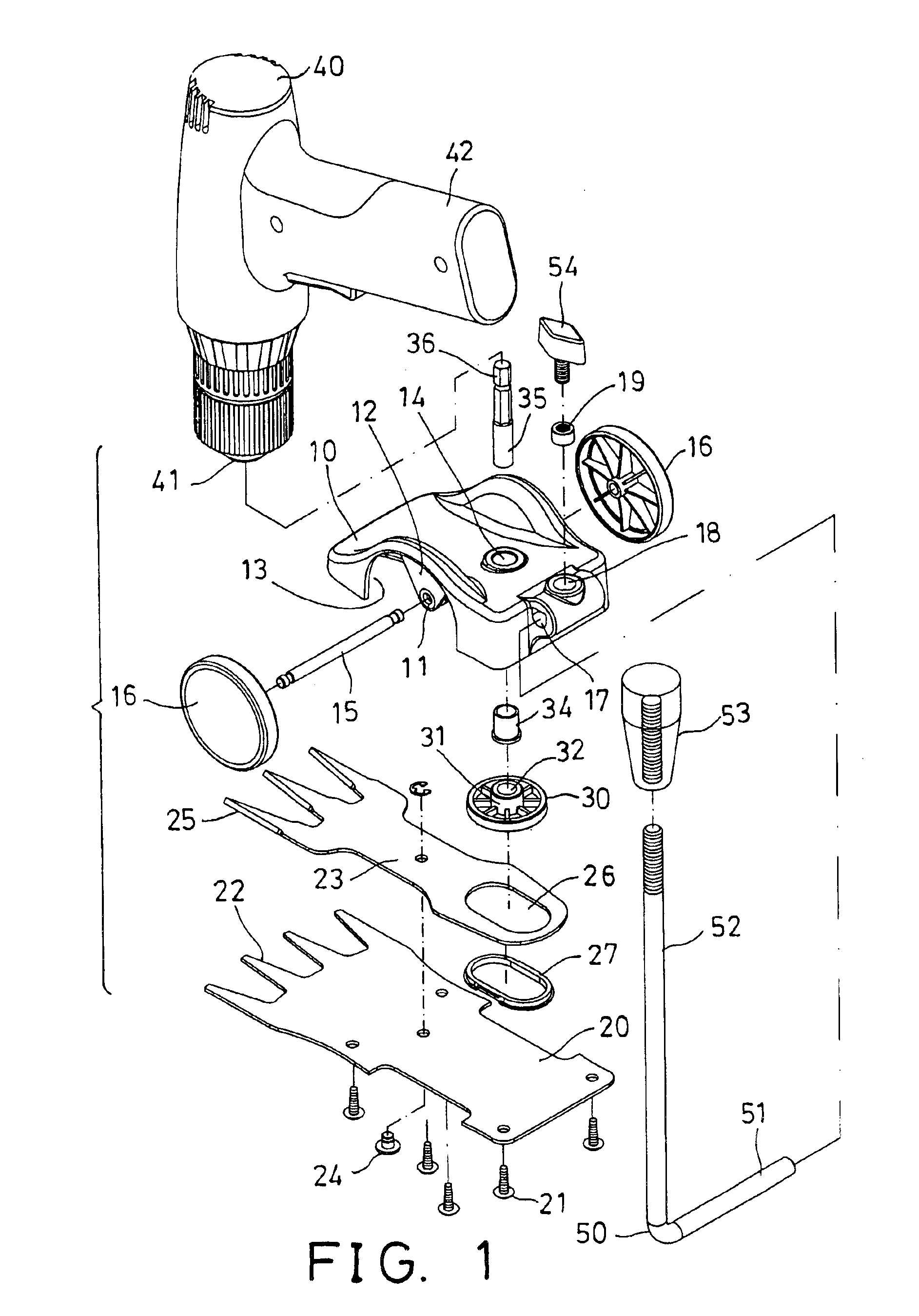
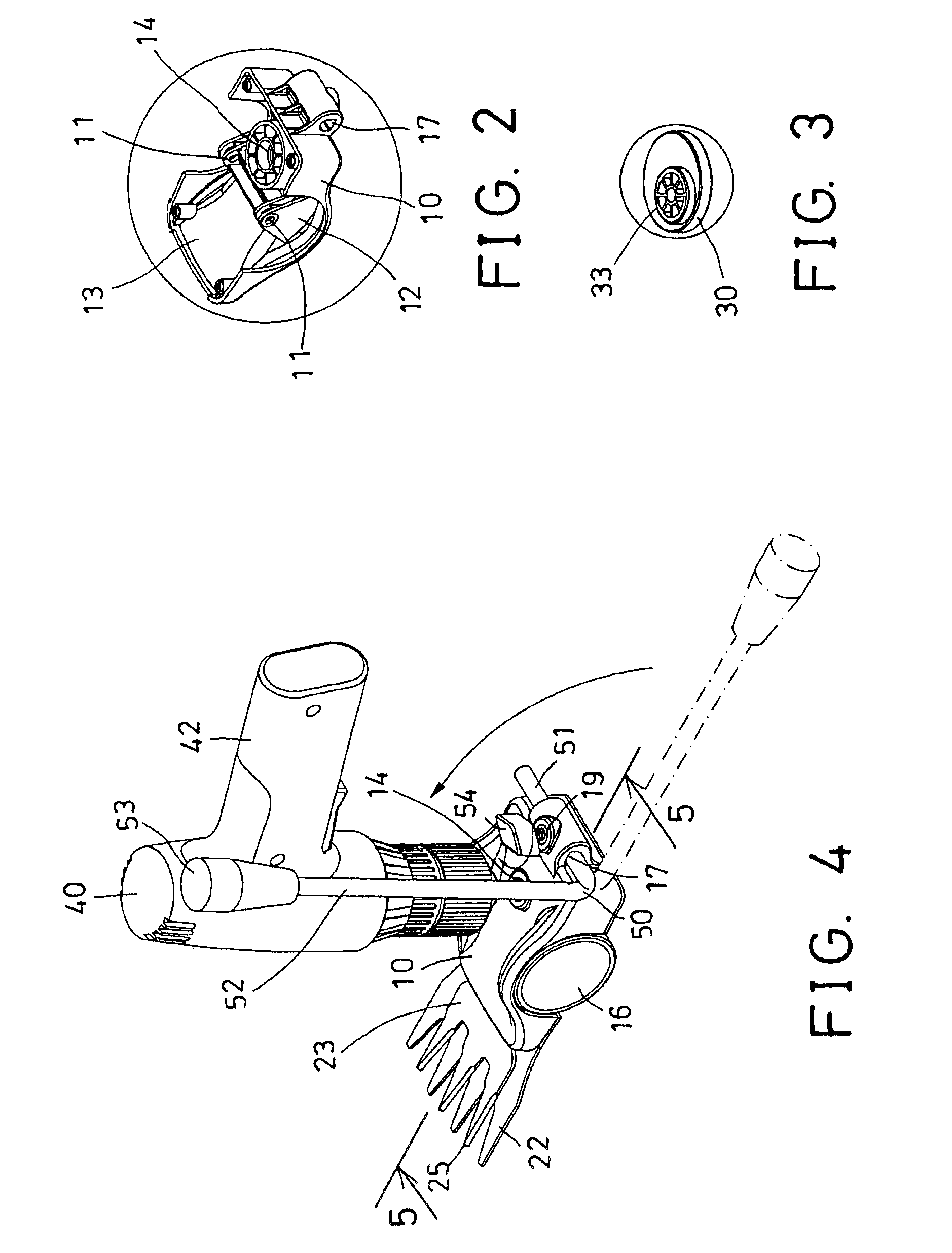
Referring to the drawings, and initially to FIGS. 1-5, a grass trimmer in accordance with the present invention comprises a housing 10 including an orifice 11 formed therein, such as including a stay 12 extended into a chamber 13 thereof and having the orifice 11 formed in the stay 12, for rotatably receiving a wheel axle 15, therein. One or more, such as two wheels 16 are attached to the wheel axle 15 and rotatable relative to the housing 10 with the wheel axle 15.

The housing 10 further includes a passage 14 formed therein, such as vertically formed therein, and communicating with the chamber 13 thereof, and includes an aperture 17 formed therein, such as laterally formed in the rear portion thereof, and further includes a hole 18 formed in the rear portion thereof, and intersecting or communicating with the aperture 17 thereof for receiving or securing or attaching a nut 19 therein, best shown in FIGS. 1 and 5.

A fixed cutter device 20 is secured to bottom of the housing 10 with su...


PUM


Abstract

A grass trimmer includes a fixed cutter device secured to a housing and having one or more stationary cutter blades extended out of the housing, a movable cutter device rotatably secured to the fixed cutter device and having one or more cutter blades movable relative to the stationary cutter blade of the fixed cutter device to conduct cutting operations by an eccentric member of a rotary member. A drive shank is secured to the rotary member, and a power tool may engage with the shank, to drive the rotary member and the eccentric member relative to the movable cutter device, and to move the movable cutter device relative to the fixed cutter device in reciprocating action.

Description

BACKGROUND OF THE INVENTION1. Field of the InventionThe present invention relates to a grass trimmer, and more particularly to a grass trimmer operatable or drivable by typical or separate power tools.2. Description of the Prior ArtVarious kinds of typical grass trimmers have been developed and comprise a motor solidly attached to or secured to a housing, for rotating or driving cutter blades.For example, U.S. Pat. No. 3,973,378 to Bartasevich et al. and U.S. Pat. No. 5,197,268 to Barrera disclose two of the typical grass trimmers each also comprising a motor solidly attached to or secured to a housing, for rotating or driving cutter blades, such that the typical grass trimmers may comprise a large volume and may be expensive for the users.U.S. Pat. No. 4,493,223 to Kishi et al. discloses one of the typical power tools for such as drilling purposes, and for rotating or driving screws, bolts, or the like. Normally, every family may have one or more typical power tools that have not b...

Claims


Application Information

Patent Timeline
IPC IPC(8): A01G3/00A01G3/06A01D34/02A01D34/08
CPCA01G3/067A01D34/08
Inventor YANG, CHUNG JENG
Owner YANG CHUNG JENG
Learn More