Breathing circuit disconnect warning system and method for using a disconnect system

a technology of disconnect warning system and breathing circuit, which is applied in the direction of respiratory organ evaluation, operating means/releasing devices of valves, diagnostic recording/measuring, etc., to achieve the effects of low manufacturing cost, convenient and efficient manufacturing and marketing, and durable and reliable construction

Inactive Publication Date: 2005-04-05
NASHED RAMSES
View PDF10 Cites 17 Cited by
  • Summary
  • Abstract
  • Description
  • Claims
  • Application Information

AI Technical Summary

Benefits of technology

It is another object of the present invention to provide a new and improved breathing circuit disconnect warning system and a method for using a disconnect system which may be easily and efficiently manufactured and marketed.
It is further an object of the present invention to provide a new and improved breathing circuit disconnect warning system and a method for using a disconnect system which is of durable and reliable constructions.
An even further object of the present invention is to provide a new and improved breathing circuit disconnect warning system and a method for using a disconnect system which is susceptible of a low cost of manufacture with regard to both materials and labor, and which accordingly is then susceptible of low prices of sale to the consuming public, thereby making such breathing circuit disconnect warning system and a method for using a disconnect system economically available to the buying public.
Even still another object of the present invention is to provide a breathing circuit disconnect warn ing sys tem and a method for using a disconnect system for allowing a user to monitor continuity within a breathing circuit thereby increasing patient safety.

Problems solved by technology

While these devices fulfill their respective, particular objectives and requirements, the aforementioned patents do not describe a breathing circuit disconnect warning system and a method for using a disconnect system that allows allowing a user to monitor continuity within a breathing circuit.

Method used


Image

  • Breathing circuit disconnect warning system and method for using a disconnect system
  • Breathing circuit disconnect warning system and method for using a disconnect system
  • Breathing circuit disconnect warning system and method for using a disconnect system

Examples


Embodiment Construction

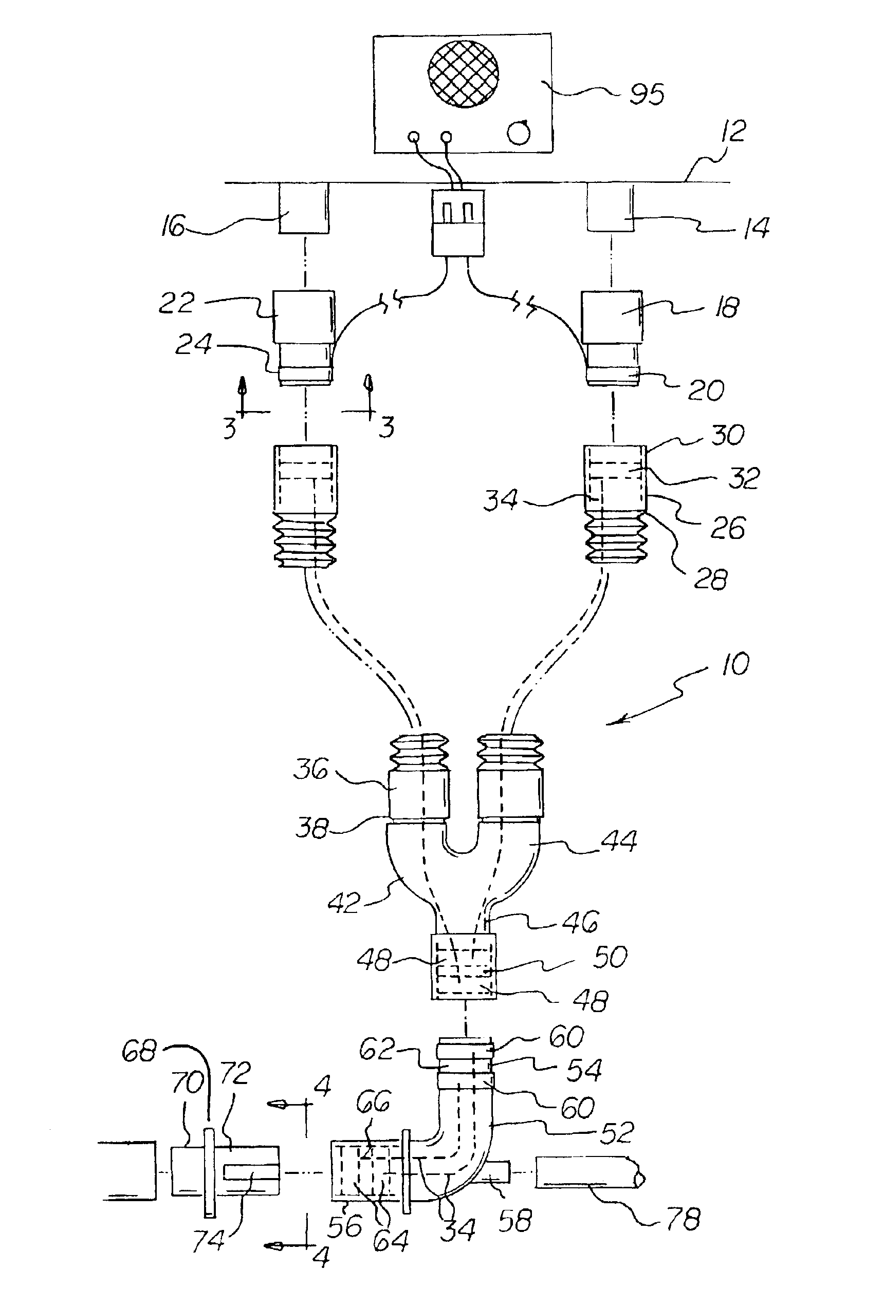
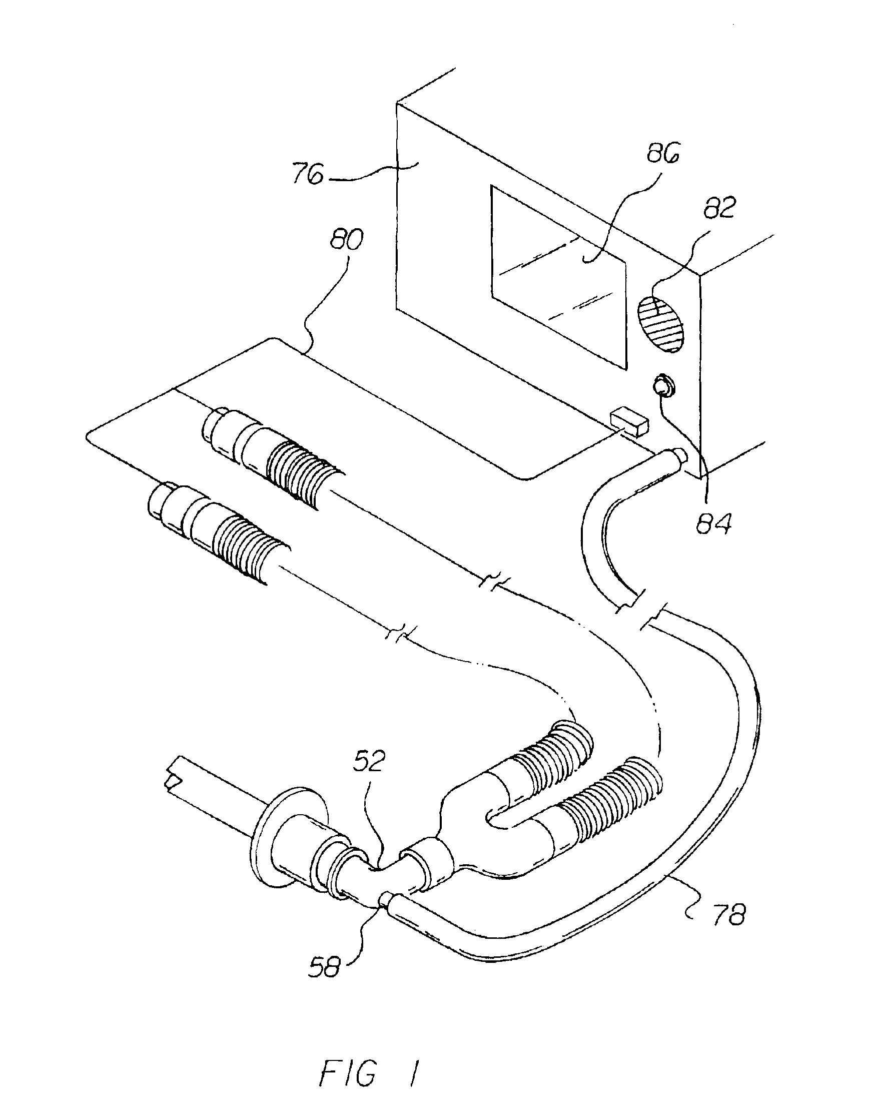
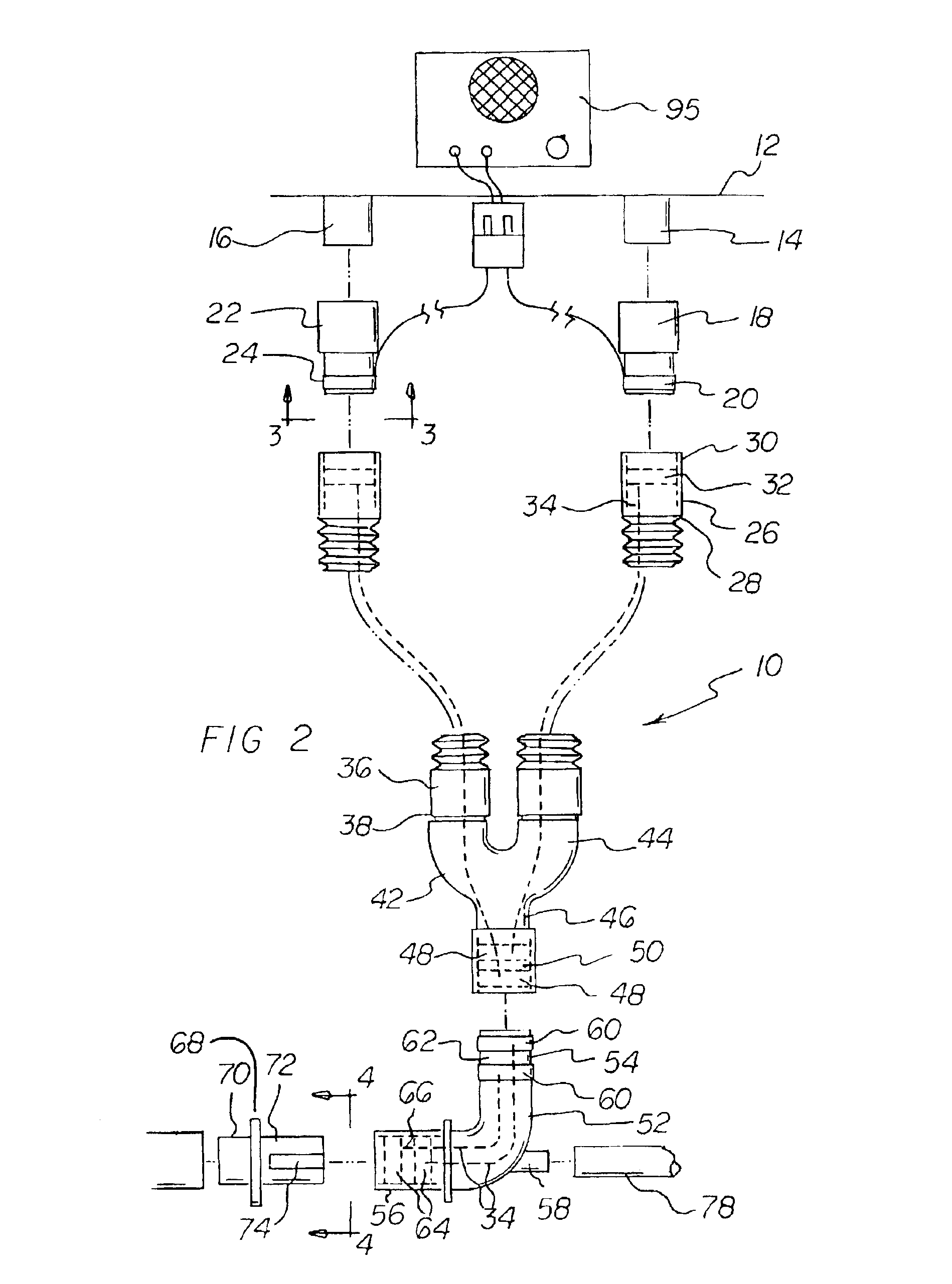
With reference now to the drawings, and in particular to FIG. 1 thereof, the preferred embodiment of the new and improved breathing circuit disconnect warning system and a method for using a disconnect system embodying the principles and concepts of the present invention and generally designated by the reference numeral 10 will be described.

The present invention, the breathing circuit disconnect warning system and a method for using a disconnect system 10 is comprised of a plurality of components. Such components in their broadest context include a gas circuit, a plurality of circuit adapters, an anesthesia breathing circuit, and an endotracheal tube. Such components are individually configured and correlated with respect to each other so as to attain the desired objective.

First provided is a gas circuit 12. The gas circuit has an outlet 14 with a first outer diameter. The gas circuit also has an inlet 16 with a first outer diameter.

A first gas circuit outlet adapter 18 is provided....


PUM


Abstract

A gas circuit has an outlet and an inlet. Circuit adapters are provided. An anesthesia breathing circuit has tubular breathing circuit hoses, a Y connector and a connecting elbow. The breathing circuit has an electronically conductive system of wires and contacts to form two unconnected parallel electric circuits. An endotracheal tube has a conductive strip. A capnograph has a sampling tube coupled to the breathing circuit. The capnograph is electrically coupled to the separate electric circuits. The capnograph begins an adjustable timer when the endotracheal connector completes the electrical circuit by connecting the endotracheal tube to the breathing circuit. The timer provides for the transmission of an alarm when the circuit had been completed and no carbon dioxide was detected in the breathing hoses within a predetermined amount of time. The timer also provides for the transmission of an alarm when the circuit had been completed and had been disconnected.

Description

BACKGROUND OF THE INVENTION1. Field of the InventionThe present invention relates to a breathing circuit disconnect warning system and a method for using a disconnect system and more particularly pertains to allowing a user to monitor continuity within a breathing circuit.2. Description of the Prior ArtThe use of disconnect warning systems of known designs and configurations is known in the prior art. More specifically, disconnect warning systems of known designs and configurations previously devised and utilized for the purpose of warning a user of a disconnect through conventional methods and apparatuses are known to consist basically of familiar, expected, and obvious structural configurations, notwithstanding the myriad of designs encompassed by the crowded prior art which has been developed for the fulfillment of countless objectives and requirements.By way of example, U.S. Pat. No. 3,796,197 issued Mar. 12, 1974, to Locher et al discloses an electronic regulator with fuel inje...

Claims


Application Information

Patent Timeline
Patent Type & Authority Patents(United States)
IPC IPC(8): A62B7/00A62B9/00A61M16/00A61M16/04A61M39/10
CPCA61M16/0051A61M16/04Y10S128/912A61M2039/1005A61M16/0816A61M2016/0413A61M16/0833A61M16/021
Inventor NASHED, RAMSES
Owner NASHED RAMSES
Why Eureka
Try Eureka