Tape dispenser having a tape retaining and application area

a tape dispenser and tape retaining technology, which is applied in the field of tape dispensers, can solve the problems of cumbersome use, difficult to pull off a roll by hand and manoeuver into position, and many of the devices, however, experience a number of problems in their use, so as to prevent the back from curling

Inactive Publication Date: 2005-04-05
CONROS +1
View PDF7 Cites 35 Cited by
  • Summary
  • Abstract
  • Description
  • Claims
  • Application Information

AI Technical Summary

Benefits of technology

The device of the present invention is a tape dispenser that has a frame, a cutter blade, a pair of tabs disposed on the interior surface of each side wall and a projection disposed proximate each tab. The dispenser holds a roll of adhesive tape therein. The tabs are positioned away from the cutter blade and they substantially do not extend below the lower edge of the side walls of the dispenser. The projections extend from the top of the tabs toward the interior of the upper surface of the dispenser. The distance between the projections is less than the distance between the interior surfaces of the side walls of the dispenser. The tabs are positioned and shaped in such a manner that tape from the roll is supported on the top surface of the tabs. The combination of the shape of the tabs and the presence of the projections causes the tape to be convexly shaped when viewed from the front of the dispenser. The arched tape is biased into contact with the front end of the dispenser by the tabs and projections so that the tape is ready to be dispensed from the roll and is prevented from curling back onto the roll when cut.

Problems solved by technology

This type of tape is typically 2 inches wide and is fairly difficult to pull off a roll by hand and manoeuver into position around a package.
Many of these devices, however, experience a number of problems in their usage.
Most adhesive tapes tend to be flimsy and easily statically charged so that when the tape is cut, the free end tends to curl back onto the roll of tape.
While this device functions well, it is cumbersome to use and has a number of moving parts that make it expensive to manufacture and prone to breakage.
A common problem with these tabs is that they are fragile and tend to break off the frame relatively easily.
They are therefore rendered useless fairly frequently.
A second problem experienced in the usage of previously known tape dispensers is that because adhesive tapes tend to be flimsy, if they are not immediately stuck down onto the surface they are being applied to, they tend to partially fold back on themselves.
When pressure is applied to smooth out and stick the tape into contact with the surface, they tend to form small pockets of tape stuck to itself instead of to the surface to which the tape is being applied.
This results in the surface having a messy appearance and in that less tape is in contact with the surface than may be desirable.
This may result in a less secured package.

Method used


Image

  • Tape dispenser having a tape retaining and application area
  • Tape dispenser having a tape retaining and application area
  • Tape dispenser having a tape retaining and application area

Examples


Embodiment Construction

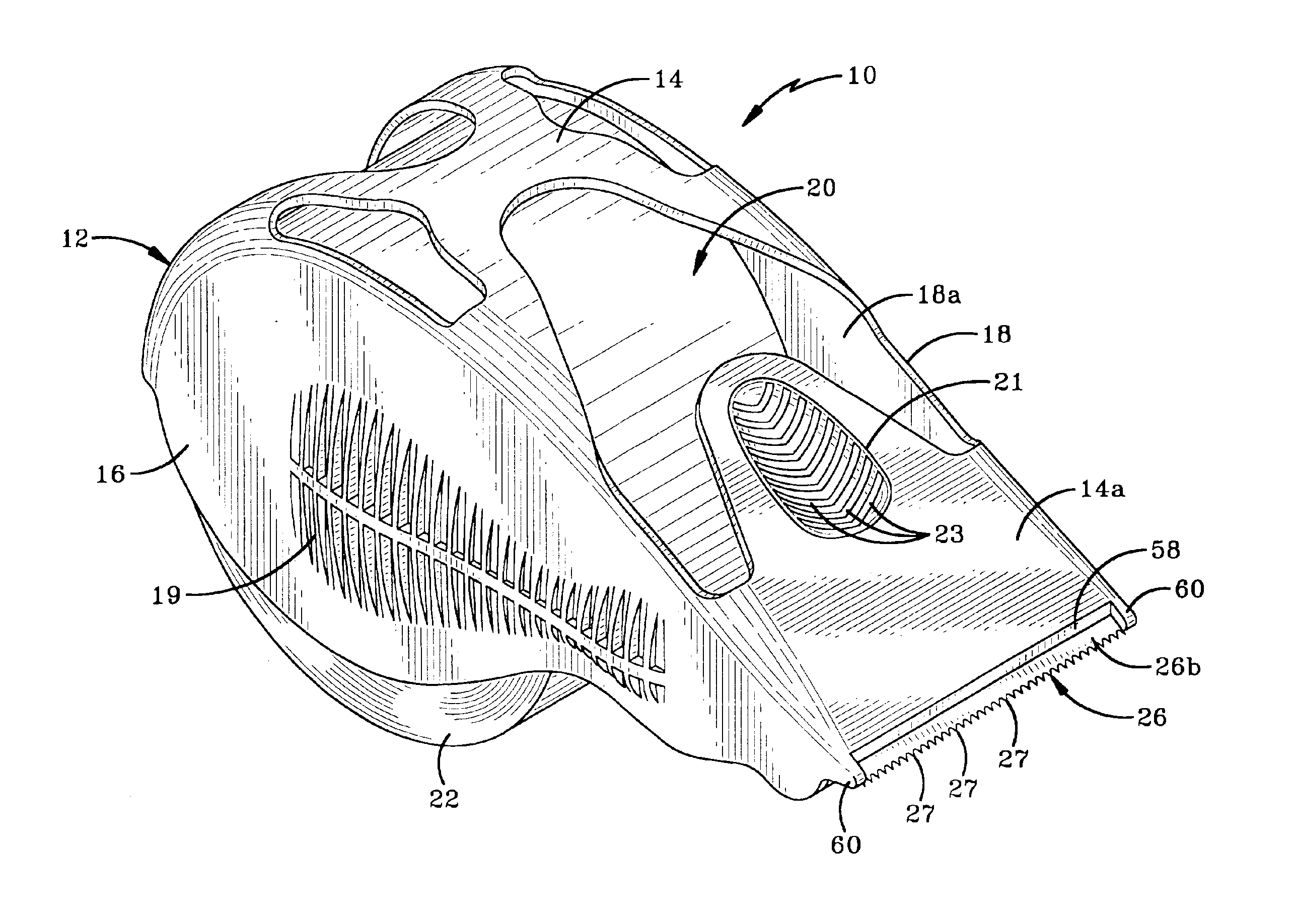
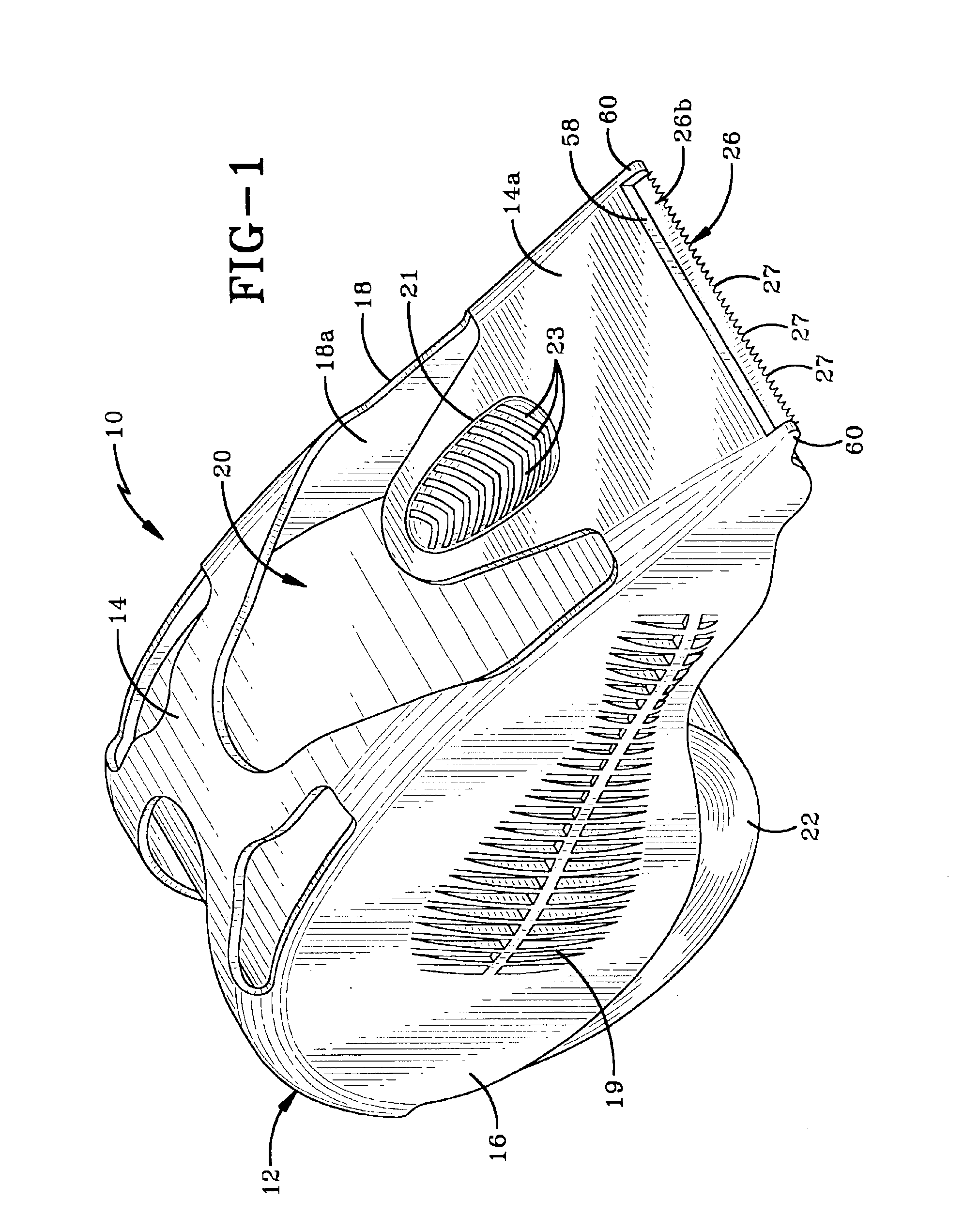
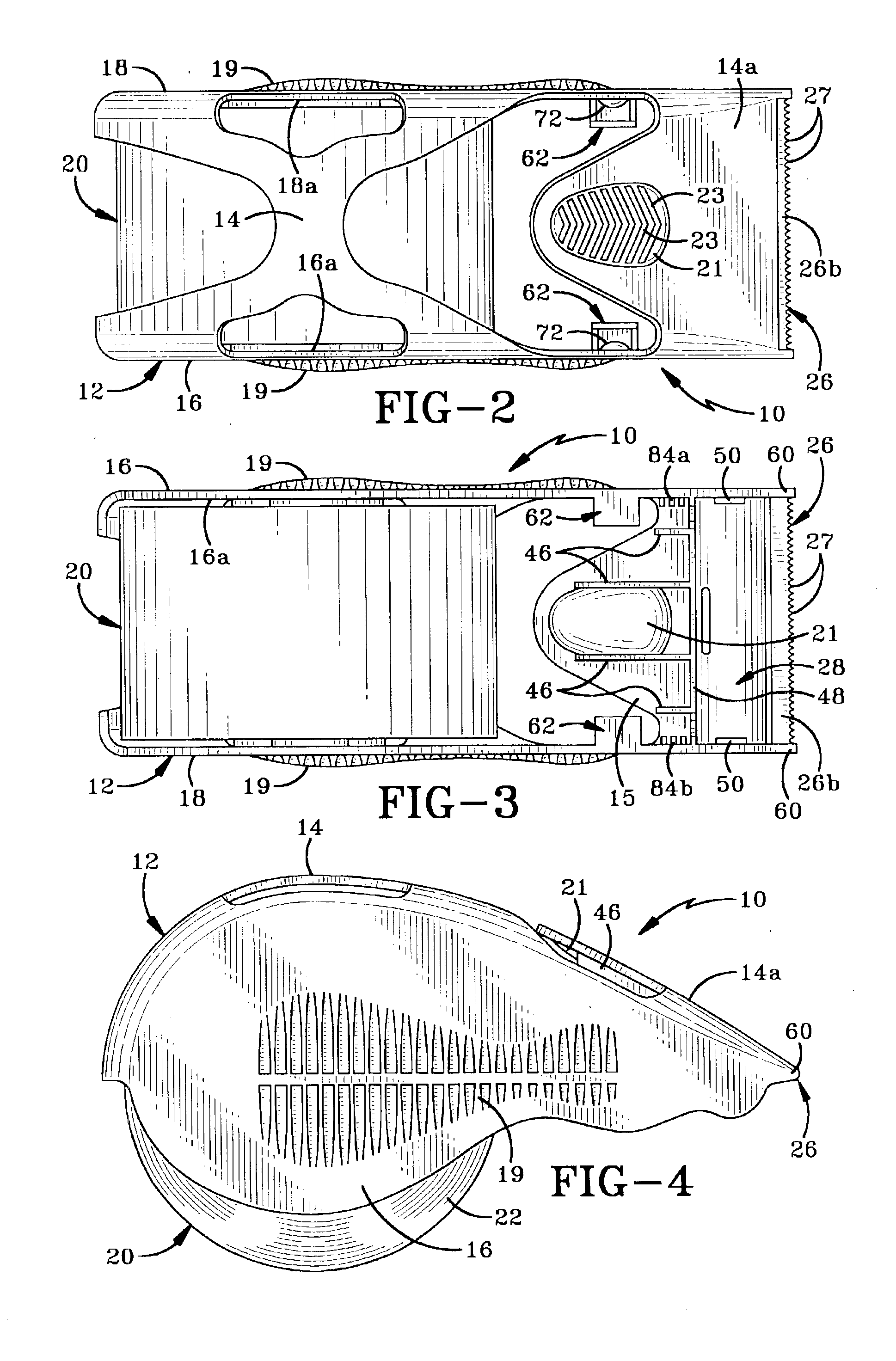
Referring to FIGS. 1-7, there is shown a tape dispenser in accordance with the present invention, the dispenser being referred to generally by the number 10. Dispenser 10 comprises a frame 12 having an upper surface 14 and opposed side walls 16, 18. A roll 20 of adhesive tape 22 is held in position in dispenser 10 by way of tape mounts or hubs 24 (FIG. 9) extending from the opposed interior surfaces 16a, 18a of side walls 16, 18. A pressure pad, generally referred to by the number 28 (FIG. 6), and a cutter blade 26 with teeth 27 are provided proximate the front portion 14a of upper surface 14.

Dispenser 10 is molded from a suitable polymeric material that allows it to be manufactured reasonably cheaply but also be relatively strong and sturdy. Preferably, dispenser 10 is molded as an integral unit and side walls 16, 18 are preferably able to flex somewhat relative to each other so as to allow a roll 20 of tape to be inserted into dispenser 10. Upper surface 14 may either be molded as...


PUM

PropertyMeasurementUnit
distanceaaaaaaaaaa
distanceaaaaaaaaaa
widthaaaaaaaaaa

Abstract

A tape dispenser having a frame, a cutter blade and at least one pair of projections disposed on the opposed interior surfaces of the side walls is disclosed. The distance between the projections is less than the distance between the interior surfaces of the side walls and is also less than the width of the tape held in the dispenser. The tape dispenser may also include a pair of tabs either associated with the projections or positioned between the projections and the tape mount. The dispenser is adapted to hold a roll of adhesive tape therein and because of the decreased distance between the projections, the tape assumes a convex shape when viewed from the front end of the dispenser. The shape of the tape and position of the tabs and projections causes the tape to be biased into contact with the interior of the front end of the dispenser. This helps to keep the free end of the tape out of contact with the roll in the dispenser.

Description

BACKGROUND OF THE INVENTION1. Technical FieldThis invention generally relates to tape dispensers. More particularly, the invention relates to hand-held tape dispensers adapted to dispense adhesive tape. Specifically, the invention relates to a hand-held tape dispenser that includes a pair of tabs and projections that aid in preventing the free end of the tape from curling back onto the roll held in the dispenser.2. Background InformationThere are numerous types of adhesive tapes that have a wide variety of uses. A frequently used type of adhesive tape is packaging tape that is used to secure the flaps of boxes and packages for shipping. This type of tape is typically 2 inches wide and is fairly difficult to pull off a roll by hand and manoeuver into position around a package. Large industrial hand-held tape dispensers have been proposed in the prior art for applying such wide adhesive tape. Many of these devices, however, experience a number of problems in their usage. Most adhesive...

Claims


Application Information

Patent Timeline
Patent Type & Authority Patents(United States)
IPC IPC(8): B65H35/00
CPCB65H35/0033Y10T156/18Y10T156/12Y10T156/1365Y10T156/1793Y10T156/1795Y10T225/282Y10T225/294Y10T225/269Y10T225/257Y10T225/285Y10T225/297
Inventor CHANDARIA, ASHOK
Owner CONROS
Why Eureka
Try Eureka