Beater bar capable of being acted upon on one side for impactor rotors

a technology of impactor rotors and beater bars, which is applied in the field of beater bars capable of being, can solve the problems of complicated and costly fixation of beater bars, beater bars flying out of their mounting, and the fastening of beater bars, so as to achieve easy installation and removal, and high wear mass

Inactive Publication Date: 2005-04-05
HAZEMAG & EPR
View PDF19 Cites 2 Cited by
  • Summary
  • Abstract
  • Description
  • Claims
  • Application Information

AI Technical Summary

Benefits of technology

Accordingly it is an object of the present invention to provide a beater bar which can easily be installed and removed in rotors of impactors and is also handy, which has a high wearing mass in relation to its total mass and which avoids the further disadvantages mentioned above.
The beater bar according to the invention, which is capable of being inserted into circumferential slots, matched to its contour, of the impactor rotors, is therefore easily exchangeable, because, on the one hand, in the installed state, there are no slots or clearances between its bearing surfaces or its supporting surface and those surfaces of the circumferential slots which correspond to these, and, on the other hand, as a result of the arrangement of the centres of rotation of the arc radii in relation to one another, the beater bar, when tilted forwards, is immediately freed from its self-locking so as to open a gap. The arrangement of the centres of rotation of the radii and of the two boundary arcs of the bend of the beater bar also result in a small clamping height of the beater bar, in that the larger outer arc delimiting the lower and front supporting surface is provided further inwards towards the rotor. It is advantageous if the distance between the centres of rotation of the radii is in a ratio of 1:7 to 1:15, preferably 1:10, to the remaining height of the beater bar.

Problems solved by technology

Fixing the beater bar in this way is complicated and costly, particularly since the parts necessary for this purpose are particularly exposed to wear at this point.
The fastening of the beater bar is also unreliable, in that, if there is inadequate maintenance or inspection, the wedges may come loose in the rotating rotor, together with their pressure screws and the other aids, thus entailing the risk that the beater bar will fly out of its mounting and cause serious damage to the impactor.
A sharp-edged undercut of the circumferential slots and the corresponding sharp-edged bend of the beater bar require accurate machining of the corresponding edges and surfaces, but are also undesirable because of the notch effects which may possibly occur here.
Whilst in the case of the first-mentioned beater bars the fastening is complicated and they have the disadvantages described in more detail above, in the case of the last-mentioned beater bars there is additionally also the problem that the slots between the beater bars and the rotor contours surrounding these become clogged with fine material and obstruct the removal which is necessary after the wear of the beater bars.
Beater bars capable of being acted upon on one side are per se uneconomic because of their low wear potential.
On account of the clearances in the form of gaps which are necessary for this purpose, even with these beater bars the gaps become clogged with fine material, and, besides, the rotation or turning of the beater bars is time-consuming and therefore costly.
Also, these known beater bars have only a low degree of utilization because of their relatively large clamping height.
However, in view of high wages, the maintenance costs are increasingly decisive as regards profitability.

Method used


Image

  • Beater bar capable of being acted upon on one side for impactor rotors
  • Beater bar capable of being acted upon on one side for impactor rotors

Examples


Embodiment Construction

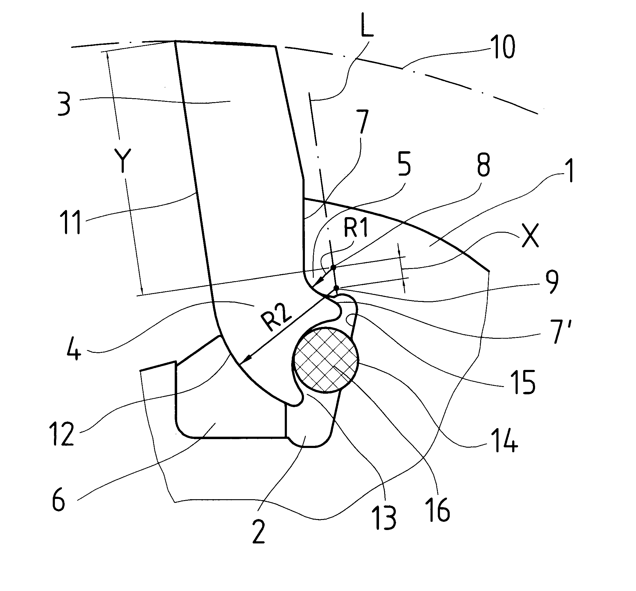
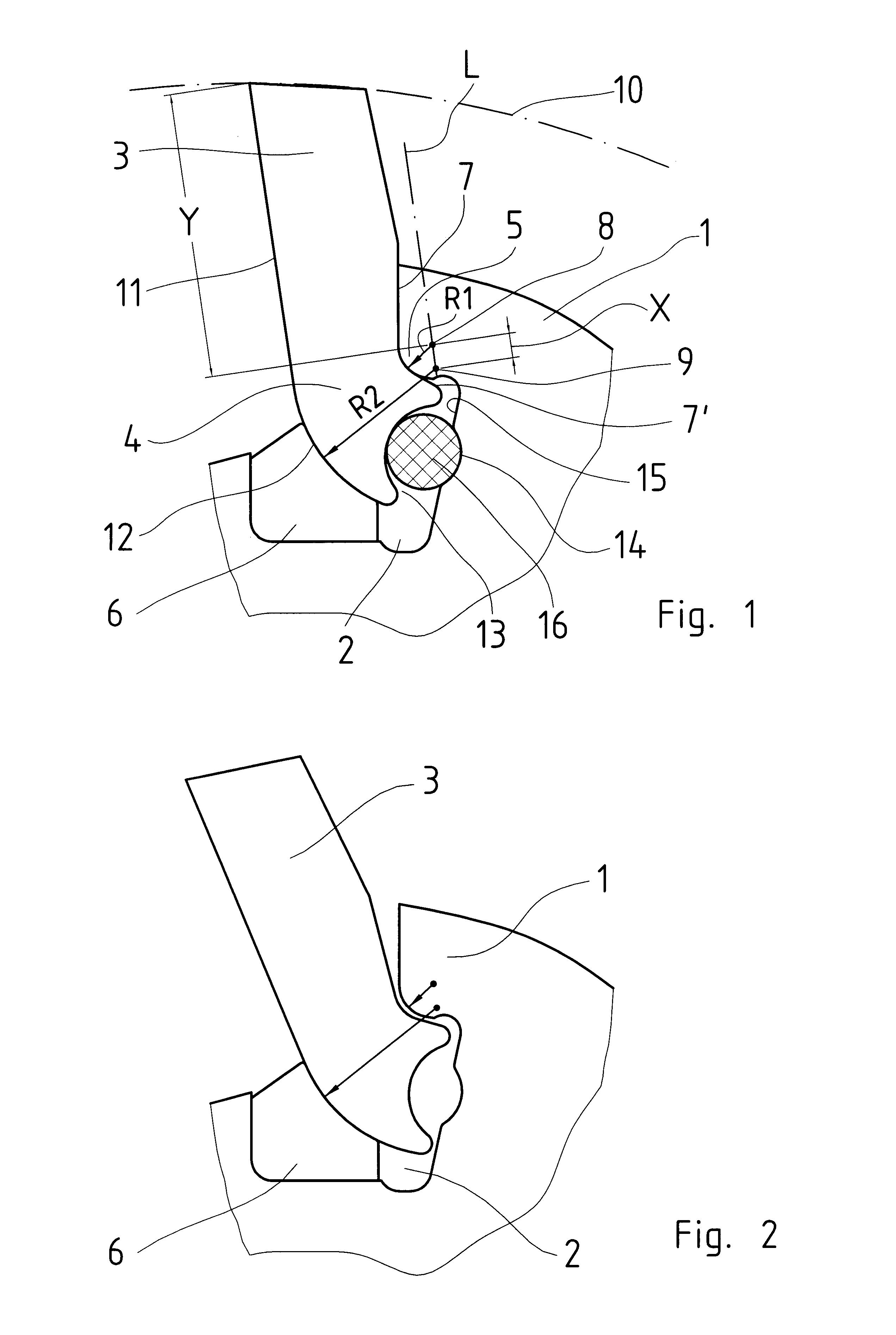
In the figures, 1 designates the detail of a casing of an impactor rotor which has circumferential slots 2 running parallel to the rotor shaft, not shown. A beater bar 3 in accordance with the present invention is pushed from the side into each circumferential slot. The beater bar has, in cross section, an elongate profile of approximately the same thickness. The beater bar is provided, at its end seated in the circumferential slot, with an arcuate bend 4, by means of which it engages under an undercut 5 of the circumferential slot. The beater bar 3 is held in engagement with the undercut by means of a supporting or bearing piece 6 which is arranged exchangeably in the base of the circumferential slot. In this case, the beater bar is supported with its bearing surface 7 against an approximately radially oriented bearing surface of the circumferential slot, with the result that the energy of the rotating rotor is conducted into the beater bar.

Due to the arcuate bend 4 of the cross se...


PUM


Abstract

A beater bar capable of being acted upon on one side for impactor rotors and insertable form-fittedly into circumferential slots of the rotors has a bend with an elongate cross-section, a bearing surface heldable counter to a centrifugal force of the rotating rotors against a bearing surface of the rotors, a supporting surface engageable with an undercut in the circumferential slot; a piece which holds the beater bar in engagement with the undercut in an circumferential slot, the bend being arcuate, and a center of rotation of a smaller radius of an arc of the bearing surfaces being at a considerable distance from a center of rotation of a larger radius of an arc of the supporting surface, so that the two centers of rotation run in a line extending approximately parallel to a beating surface, the bearing surfaces being at an obtuse angle to one another in a prolongation of the smaller arc.

Description

BACKGROUND OF THE INVENTIONThe present invention relates to a beater bar capable of being acted upon on one side for impactor rotors.More particularly, it relates to a beater bar which is capable of being inserted form-fittedly into circumferential slots of the rotors and which has rearwards, opposite to the direction of rotation of the rotors, and facing these, a bend of its elongate cross section, by means of which it engages into a longitudinally running undercut of the circumferential slots and is held counter to the centrifugal force of the rotating rotors, with bearing surfaces, by means of which the beater bar is held against a bearing surface of the rotors, and with a supporting surface, via which the beater bar is in engagement with the undercut in the circumferential slots by means of a supporting or bearing piece.A beater bar of this type is known from U.S. Pat. No. 3,151,816. It has, on its rear side, a right-angled bend which engages under an undercut of the bearing sur...

Claims


Application Information

Patent Timeline
Patent Type & Authority Patents(United States)
IPC IPC(8): B02C13/00B02C13/06B02C13/28
CPCB02C13/2804B02C13/06
Inventor HEUKAMP, VOLKERHEMESATH, GERHARD
Owner HAZEMAG & EPR
Why Eureka
Try Eureka