Direction regulator of display

a display and direction regulation technology, applied in the direction of shutters/movable grilles, identification means, instruments, etc., can solve the problems of difficult suppression of the increase of the inability to rotate and adjust the monitor, and the number of parts, so as to achieve constant force and ease of movement. , the effect of not easily displaced the movement position of the display

Inactive Publication Date: 2005-04-05
MURAKAMI CORP +1
View PDF14 Cites 120 Cited by
  • Summary
  • Abstract
  • Description
  • Claims
  • Application Information

AI Technical Summary

Benefits of technology

Specifically, the device for adjusting a direction of a display according to the present invention having the configuration described above, can reduce a number of parts making up the mechanism for supporting a display, whereby the adjustment of an angle of the display in the 90° revolution direction, a vertically tilting direction and horizontal direction at a substantial constant position can easily be performed only by a simple construction and a reduced number of parts.
Moreover, since the center of rotating the display is designed to be substantially accorded with the center of the gravity, the user can always adjust the direction of the display always at a constant force with ease. Also, even if vibration or such occurs, the movement position of the display is not easily displaced.

Problems solved by technology

However, the elevating device for ascending or descending a liquid crystal monitor disclosed in Japanese Model disclosed above cannot rotate and adjust the monitor in horizontal tilting direction at the rotation around the vertical axis (not shown), unless the frame base 300 itself rotates in the horizontal direction.
In addition, since the first supporting mechanism 201A and the second supporting mechanism 201B are separately assembled, the number of parts making up them is increased according to the increasing of the direction to be adjusted, making it difficult to suppress the increasing of the number of the parts.

Method used


Image

  • Direction regulator of display
  • Direction regulator of display
  • Direction regulator of display

Examples


first embodiment

the present invention will now be specifically described by referring to the drawings.

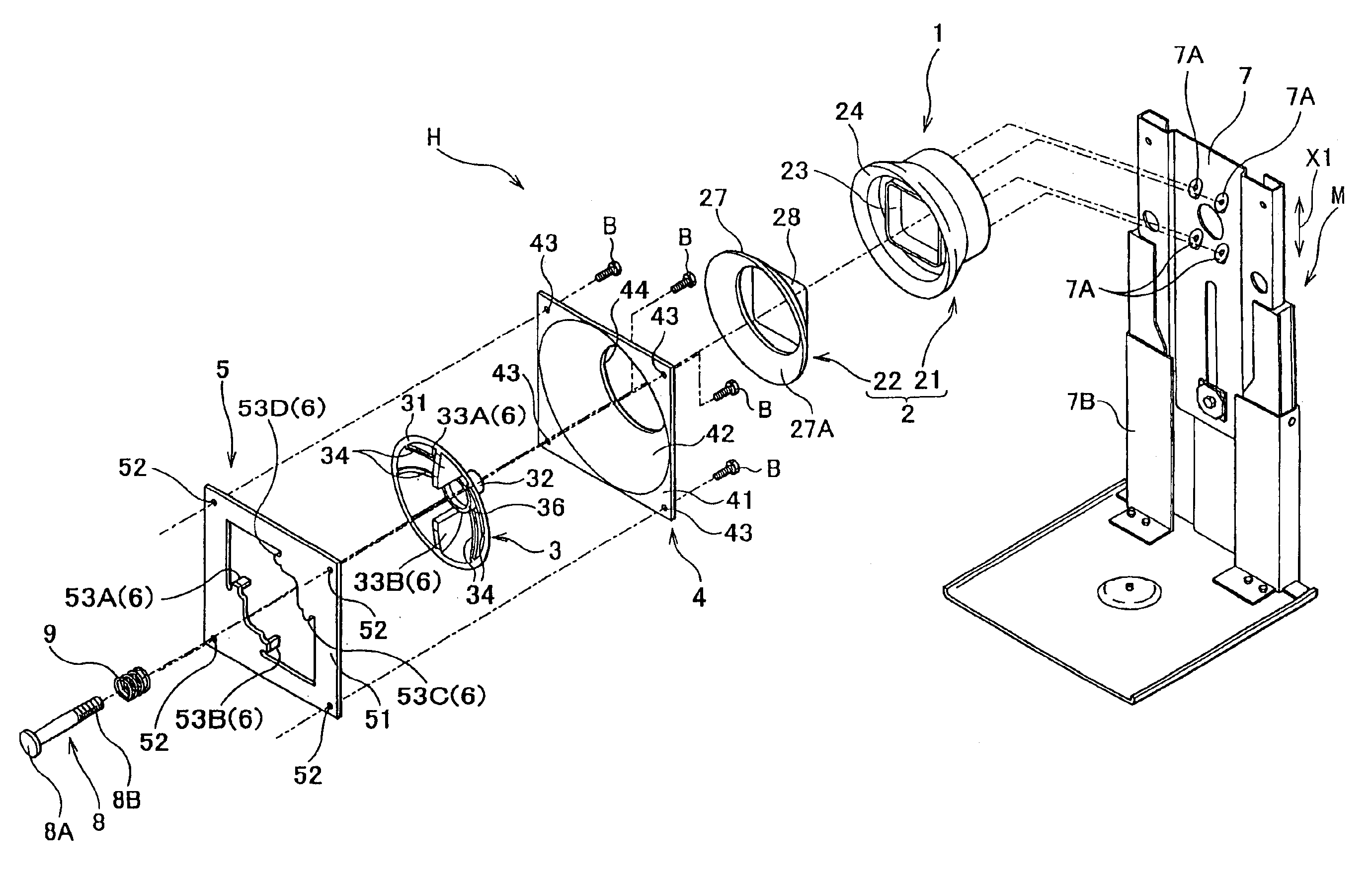
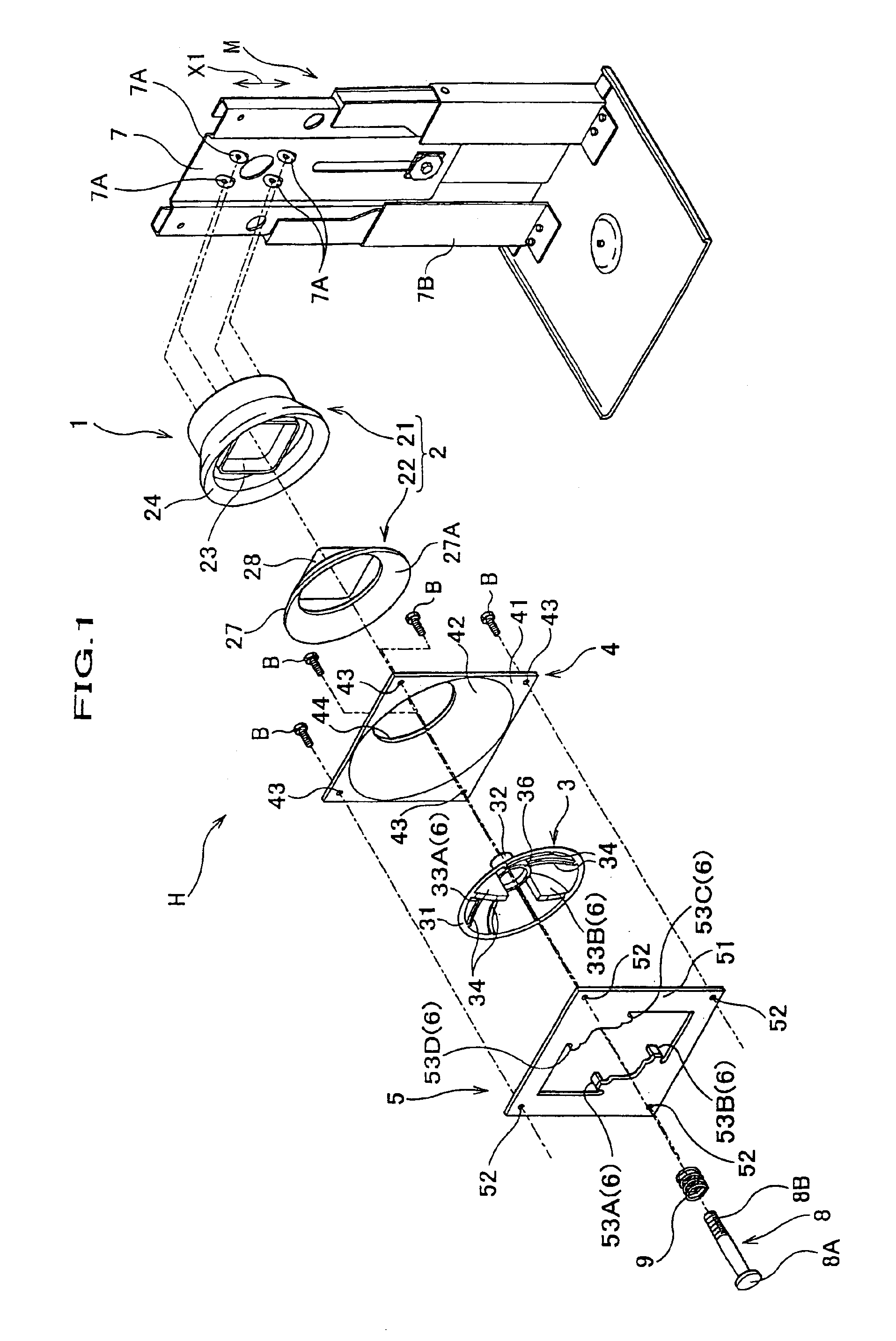
FIG. 1 is an exploded perspective view showing the device for adjusting a direction of a display according to the first embodiment partially showing the main portions.

As shown in FIG. 1, a device H for adjusting a direction of a display according to the present invention has a frame M, and a display mounter 1 is provided on an upper portion of the frame M. The display mounter 1 has a base member 2, a cap supporting member 3, a flange 4, and a member 5 for regulating an angle. Also, the cap supporting member 3 is provided in front of the base member 2, and the flange 4 is provided between the cap supporting member 3 and the base member 2. Furthermore, the member 5 for regulating an angle, by which the display is supported is provided in front of the cap supporting member 3. Stoppers 6 are provided on the cap supporting member 3 and the member 5 for regulating an angle in order to regulate the slidin...


PUM


Abstract

A direction regulator H of display, comprising a frame M mounting a member 7 capable of elevating / lowering in the height direction X1. A display fixing part 1 is provided to an upper part of the elevating / lowering member 7. The display fixing part 1 comprises a base member 2 having a spherical receiving face 27A. In front of the base member 2, a cap support 3 comprising a spherical cap body 31 having a curvature substantially identical to that of the receiving face 27A is provided to be urged by a spring 9 through the receiving face 27A of the base member 2. A flange 4 is clamped between the base member 2 and the cap support 3. The flange 4 is slidable along the spherical receiving face 27A of the base member 2. The flange 4 is fixed with a display D through an angle regulating member 5.

Description

TECHNICAL FIELDThe present invention relates to a device for adjusting a display, which supports a display such as CRT for personal computer or a television set, a liquid crystal display, a plasma display or a display utilizing LED in a manner so as to freely adjust the angle of the display.BACKGROUND ARTSIn recent years, a display for displaying an image such as for a personal computer system or a television set has been intended to be light weight. Such a type of the display is mounted in front of a frame base possessed by a device for supporting a display in such a manner as to freely adjust the angle, whereby the direction of the display can be changed to meet the favorite of a user.As an example of the device for supporting a display, an elevating device for ascending or descending a liquid crystal monitor as disclosed in Japanese Utility Model No. 3063920. As shown in FIG. 11, the elevating device for ascending or descending a liquid crystal monitor possesses a first supportin...

Claims


Application Information

Patent Timeline
Patent Type & Authority Patents(United States)
IPC IPC(8): F16M11/12F16M11/20F16M11/24F16M11/02F16M11/10G09F9/00H04N5/64
CPCF16M11/10F16M11/105F16M11/12F16M11/2078F16M11/24Y10S248/917F16M2200/048Y10S248/919Y10S248/921G06F1/16
Inventor WATANABE, ATSUSHIHIRASAWA, KENICHI
Owner MURAKAMI CORP
Why Eureka
Try Eureka