
Angled-slit bite-valve

a technology of angled slits and valves, which is applied in the direction of valve operating means/release devices, functional valve types, liquid transfer devices, etc., can solve the problems of not optimizing the use of geometry to optimize both the flow rate and sealing capabilities, and the valve can have problems with sealing, etc., to achieve the effect of low cos

Inactive Publication Date: 2005-04-05
STECKEL ERIC S
View PDF3 Cites 17 Cited by
  • Summary
  • Abstract
  • Description
  • Claims
  • Application Information

AI Technical Summary

Benefits of technology

"The new bite valve has two slits that seal tightly at low to moderate pressures and can deliver flow rates at least two times faster than valves with a single slit. It is made from a single elastomeric element and is slit in a second operation, making it a low-cost option. The valve has a rectangular cross-section with a concavely biased septum that folds on itself when pinched, allowing fluid to flow through two semi-circular paths. The valve can have multiple septum faces with angled slits, and the faces can form a chevron shape."

Problems solved by technology

These valves can have problems with sealing, even under minimal or no positive pressure.
Configurations of bite-valves with more than one slit have been developed but have not maximized the use of geometry to optimize both the flow rate and sealing capabilities as disclosed in U.S. Pat. No. 5,601,207, issued Feb. 11, 1997.

Method used


Image

  • Angled-slit bite-valve
  • Angled-slit bite-valve
  • Angled-slit bite-valve

Examples


Embodiment Construction

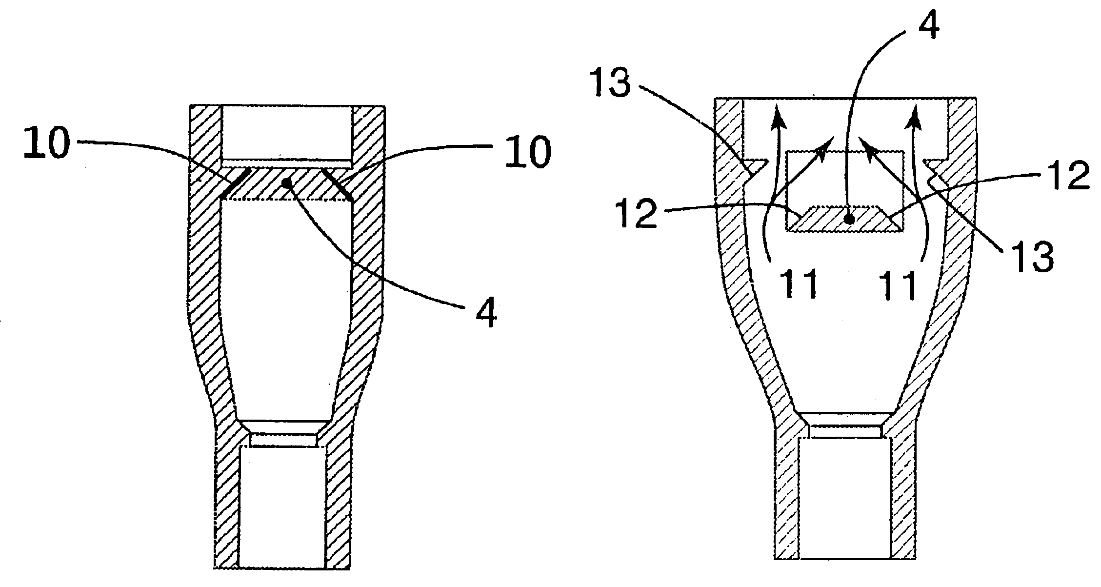
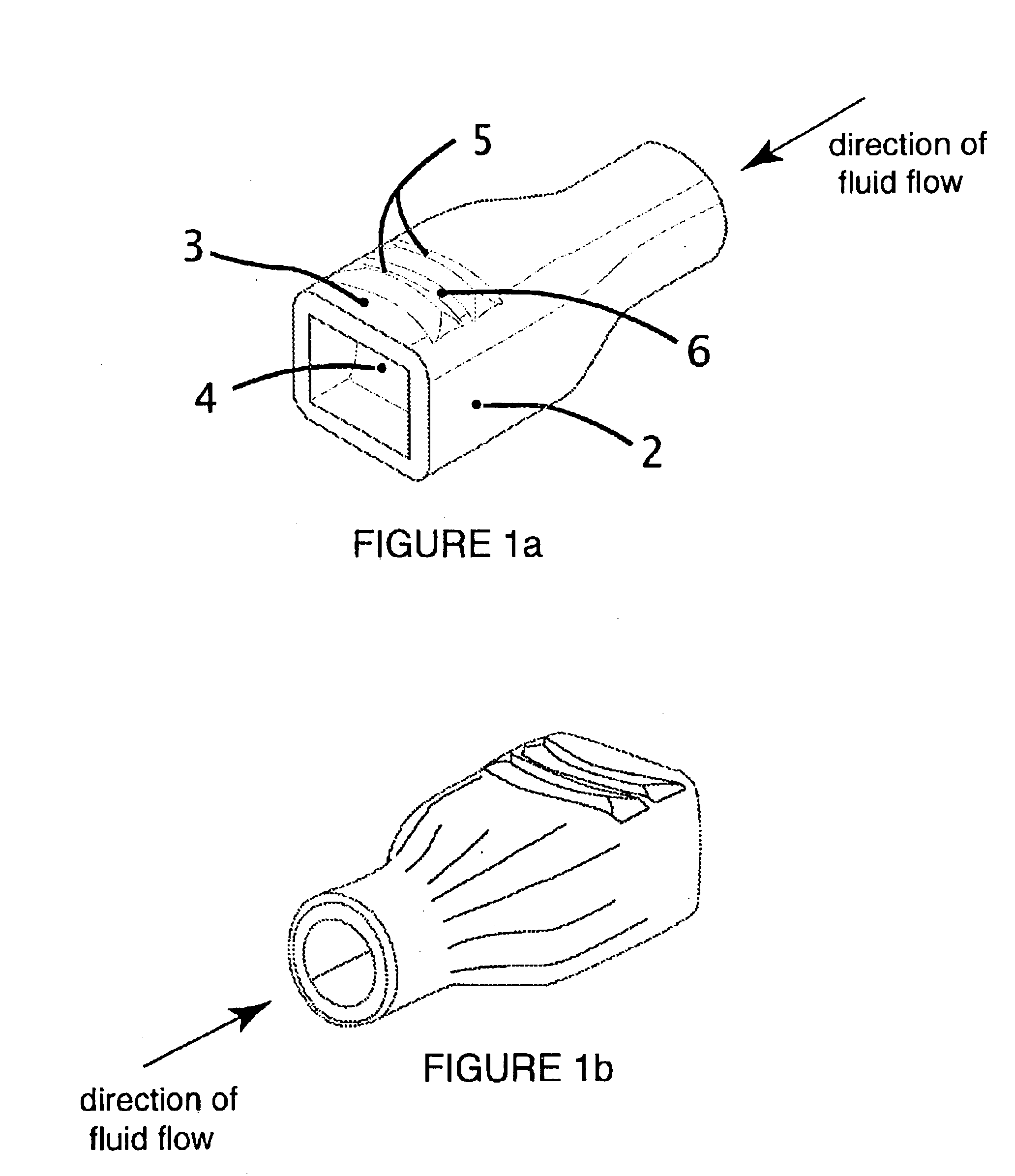
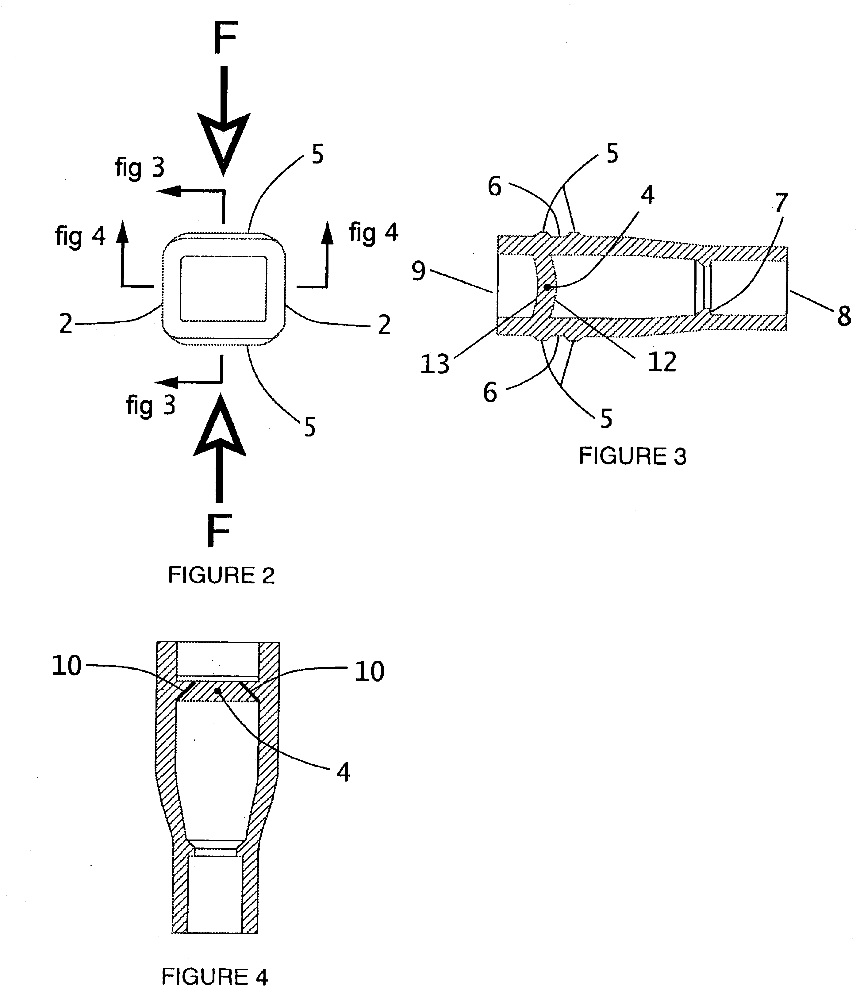
FIG. 1 is an isometric view of Bite Valve 1 depicting features Vertical Wall 2, Horizontal Wall 3, Septum 4, Bite Ridges 5, and Bite Groove 6. Applying a force in the direction of the arrows in FIG. 2 results in the formation of Fluid Paths 11 when the Vertical Walls 2 bulge outwardly away from each other while Septum 4 folds on itself (reference FIG. 5, FIG. 6, FIG. 7). Septum 4 is curved in its cross section with the concavity facing towards the Fluid Exit 9 and is slit through at an angle from the external Dry Surface 13 towards internal Wet Surface 12 such that the Septum 4 on the dry / Fluid Exit 9 side is more narrow than the opposite Fluid Entry 8 side. The mechanics of the Angled Slit 10 and the curved profile of Septum 4 compliment each other such that a better seal is formed under positive pressure than when there is no pressure. Fluid pressure acting on the Wet Surface 12 imparts a separating force against the Horizontal Walls 3 that results in a compressive force in the Se...


PUM


Abstract

Bite-valves are synonymous with personal hydration systems. Their action is to provide regulation of fluid that is drawn from the hydration reservoir by supplying a vacuum or by sucking like on a straw. Bite valves are placed in line and usually at the end of the line with the tube or hose that communicates with the reservoir. Bite-valves are normally closed and are opened when the person performs a biting action on the valve itself. Bite valves should provide the user with a perfect seal, high flow characteristics, and be small in size. Slit-type valves today are kinematically inefficient and as a consequence their flow rates are relatively slow compared to the inventor's bite-valve. This valve made of elastomeric material incorporates two angled slits along opposing vertical edges that are perpendicular to the biting direction or action. The general shape of the cross section at the site of the slitted septum is rectangular. The rectangular geometric shape is important in the flow dynamics of this valve. The septum, set back from the orifice's edge, is concavely biased towards the exit and is slit vertically at an angle such that the aperture is narrower on the exit side than on the fluid side and its purpose is to promote sealing at positive fluid pressures. When the bite-valve is pinched as from a biting action the concavely biased septum folds on itself while the side walls bulge away from each other, and form two fluid paths of a semi-circular cross section, one on each side. In addition to the formation of two fluid paths they are smooth in transition from the tubular central path and allow for flow rates almost twice that of bite-valves with a single slit of similar size.

Description

BACKGROUND AND RELATED ARTBite-valves were developed in synchrony with reservoirs containing fluids to be drawn by action of sucking by the user. These systems have since become termed personal hydration systems. Bite valves are placed in line and usually at the end of the line with the tube or hose that communicates with the reservoir. The function of a bite-valve is to provide fluid regulation by action of biting. Bite-valves are normally closed and are opened when the person performs a biting action on the valve itself. In recent years bite valves have been developed using many different methods. Vent simple bite valves have been designed comprising a single straight-slit centered on the face of a piece of elastomeric material, and when the valve is compressed by action of biting, the slit opens such that an elliptical orifice is rendered through which the fluid flows. These valves can have problems with sealing, even under minimal or no positive pressure. Flow rates associated w...

Claims


Application Information

Patent Timeline
Patent Type & Authority Patents(United States)
IPC IPC(8): F16K15/14
CPCF16K15/147
Inventor STECKEL, ERIC SAMUEL
Owner STECKEL ERIC S
Learn More