Multifocal contact lens

a contact lens and multi-focal technology, applied in the field of multi-focal contact lenses, can solve the problems of reducing the ability of natural lenses to focus on near objects, affecting the performance of lenses for near vision or distance vision, and reducing the eccentricity of the lens

Inactive Publication Date: 2005-04-05
BAUSCH & LOMB INC
View PDF5 Cites 52 Cited by
  • Summary
  • Abstract
  • Description
  • Claims
  • Application Information

AI Technical Summary

Benefits of technology

According to the invention there is now provided an improved multifocal contact lens construction and a method for fabricating a contact lens. According to one embodiment the lens is formed with two focusing zones positioned about a center point of the lens. A first optic zone is formed in a center area of the lens, providing a first power correction for distance vision. A second optic zone is formed concentrically about and contiguous with the first optic zone. The second zone provides a second power correction for near vision beginning at the junction with the first zone and extending radially outward from the junction. Preferably, the first power correction for distance vision is positioned in a most central inner portion of the first optic zone. The first optic zone also includes an outer portion contiguous with the inner portion and characterized by an increasing eccentricity that imparts a power gradient which increases the power up to the second power correction at the junction. Preferably, the power correction in the central inner portion of the first zone is relatively constant, as a function of distance from the center of the lens, in comparison to the power gradient throughout the outer portion of the first optic zone.
According to a method of making a contact lens having a for

Problems solved by technology

Presbyopia limits the ability of the natural lens to focus upon near objects.
Many designs of multifocal contact lens products have become available, but various limitations have resulted in unsatisfactory visual acuity under certain conditions.
With this variation the lens performance for near vision or distance vision may be compromised.
While this approach addresses the need for a more balanced throughput at various levels of i

Method used


Image

  • Multifocal contact lens
  • Multifocal contact lens
  • Multifocal contact lens

Examples


Embodiment Construction

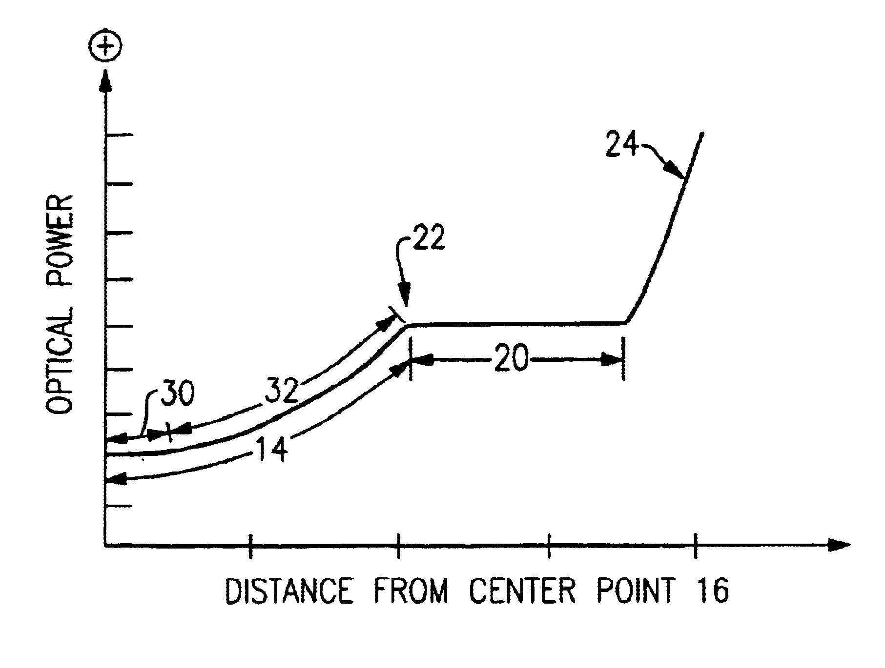
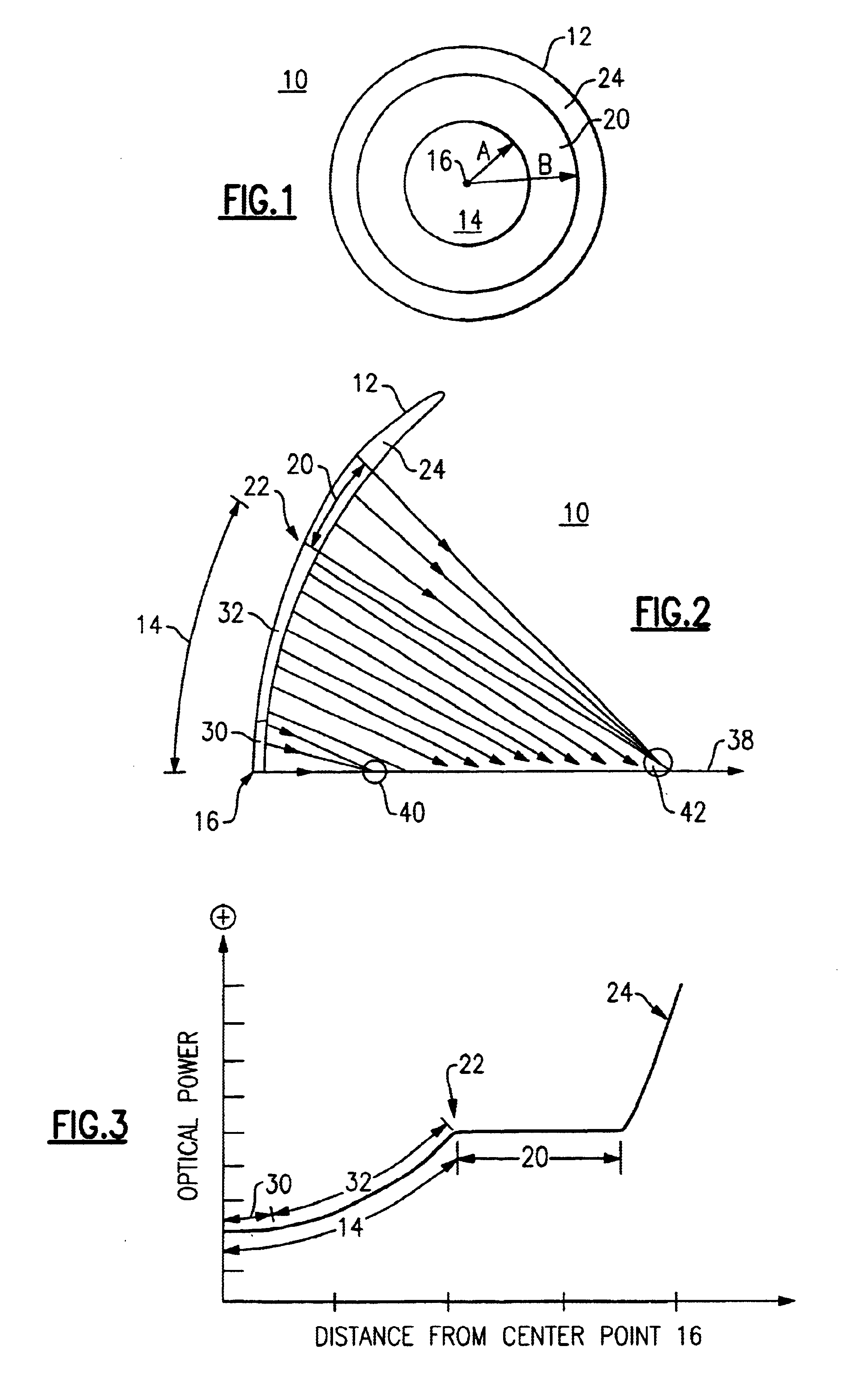
According to an exemplary embodiment of the invention a lens 10 having a front surface 12 is shown in the schematic view of FIG. 1. The lens 10 may be of the Rigid Gas Permeable (RGP) type or may be a soft lens and for purposes of illustration may be assumed to have a total diameter of 9.6 mm. Other exemplary dimensions are based on this diameter. A first rotationally symmetric central zone 14 is formed along the surface 12. The zone 14 extends from a central point 16 outwardly along the lens surface a distance A. By way of example, A may be about 2.5 mm, but more preferably will be about 3.25 mm.

A second rotationally symmetric zone 20 extends outward along the surface 12 from the first zone 14 to a distance B measured from the central point 16. The distance B may be on the order of about 3.5 mm to about 4.0 mm. The zones 14 and 20 meet at a circular shaped junction 22 which is symmetrically centered about the point 16. The combination of the zone 14 and the zone 20 provide the opti...


PUM


Abstract

A multifocal contact lens includes a first, central zone for distance and intermediate vision and a second, outer zone for near vision. The first and second zones are conic sections joined tangentially at their junction. The power in the distance subregion is relatively constant, while the power throughout the intermediate subregion is a monotonically increasing function which reaches the near power correction at the junction. The second zone includes an aspheric surface having an eccentricity calculated to minimize or eliminate spherical aberration. The slope or power gradient in the intermediate subregion is calculated to provide a smooth transition from the lower power distance subregion to the junction between the intermediate subregion and the near power correction zone.

Description

FIELD OF THE INVENTIONThe present invention relates to a multifocal contact lens and, more particularly, provision of a lens that provides correction for near, distant and intermediate vision.BACKGROUND OF THE INVENTIONIn the past, numerous designs have been proposed for multifocal contact lenses. One of the desires in the art has been to provide a contact lens solution that more satisfactorily addresses the condition of presbyopia, caused by the loss of elasticity or flexibility of the eye's crystalline lens. Presbyopia limits the ability of the natural lens to focus upon near objects. For the patient needing the combination of near vision correction and far vision correction, conventional solutions have included bifocal glasses, the combination of contact lenses, providing distance correction only, with reading glasses, and the provision of a pair of contact lenses each having a different prescription, i.e., a first lens providing one eye with distance correction and a second lens...

Claims


Application Information

Patent Timeline
IPC IPC(8): G02C7/04
CPCG02C7/044G02C7/042
Inventor TYSON, MARK K.
Owner BAUSCH & LOMB INC
Why Eureka
Try Eureka