
Osteo-arthritis knee brace

a knee brace and osteoarthritis technology, applied in the field of knee braces, can solve the problems of pain, stiffness and swelling, affecting the function of the lower leg flexion at the knee joint, and the impact between the upper brace portion and the hinge, so as to improve the curvature of the leg and facilitate the treatment of osteoarthritis

Inactive Publication Date: 2005-04-05
OSSUR HF
View PDF77 Cites 66 Cited by
  • Summary
  • Abstract
  • Description
  • Claims
  • Application Information

AI Technical Summary

Benefits of technology

The present invention is a knee brace for supporting a leg of a wearer with osteo-arthritis. The brace includes a lateral hinge component and a medial hinge component positionable respectively laterally and medially adjacent the knee joint of the wearer. There is also an upper member at least partially surroundingly encompassable about an upper leg portion situated above the knee joint of the wearer. The brace allows for flexion of the lower leg at the knee joint while also providing inward-outward selectable angularity of the upper member to treat osteo-arthritis by maintaining a non-curvature leg profile. The brace can be fitted with length-adjustable straps for securement thereof to the leg.

Problems solved by technology

Especially vulnerable are knee joints where chronic breakdown of cartilage leads to pain, stiffness, and swelling.
However, while this prior art brace with angularly-sideways adjustability addresses leg curvature, its functionality with respect to lower-leg flexion at the knee joint is impeded because certain interfacing hinge and brace members are not complimentarily configured for cooperating juxtaposed movement.
Consequently, certain lateral-angle dispositions of the upper brace portion in relation to the lower portion cause an impact between the hinge and upper brace portion upon attempted full flexion by the wearer.
This interference results in prohibiting full flexion and thereby can impede full mobility for the wearer.

Method used


Image

  • Osteo-arthritis knee brace
  • Osteo-arthritis knee brace
  • Osteo-arthritis knee brace

Examples


Embodiment Construction

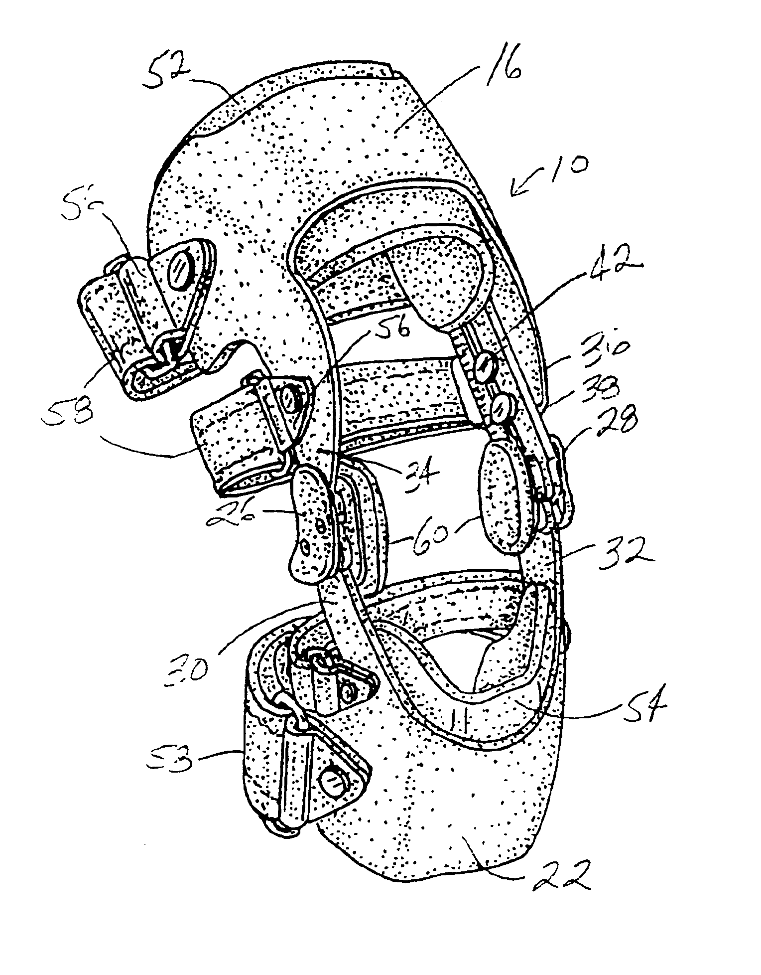
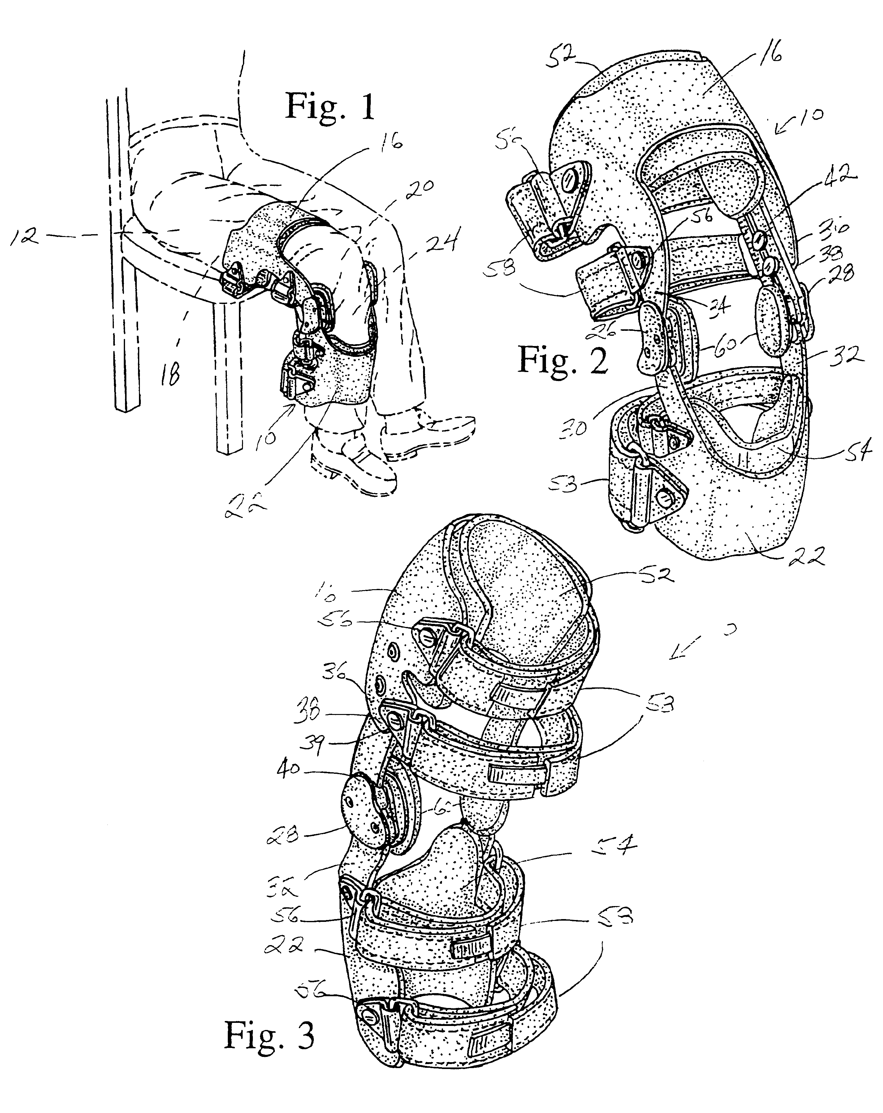
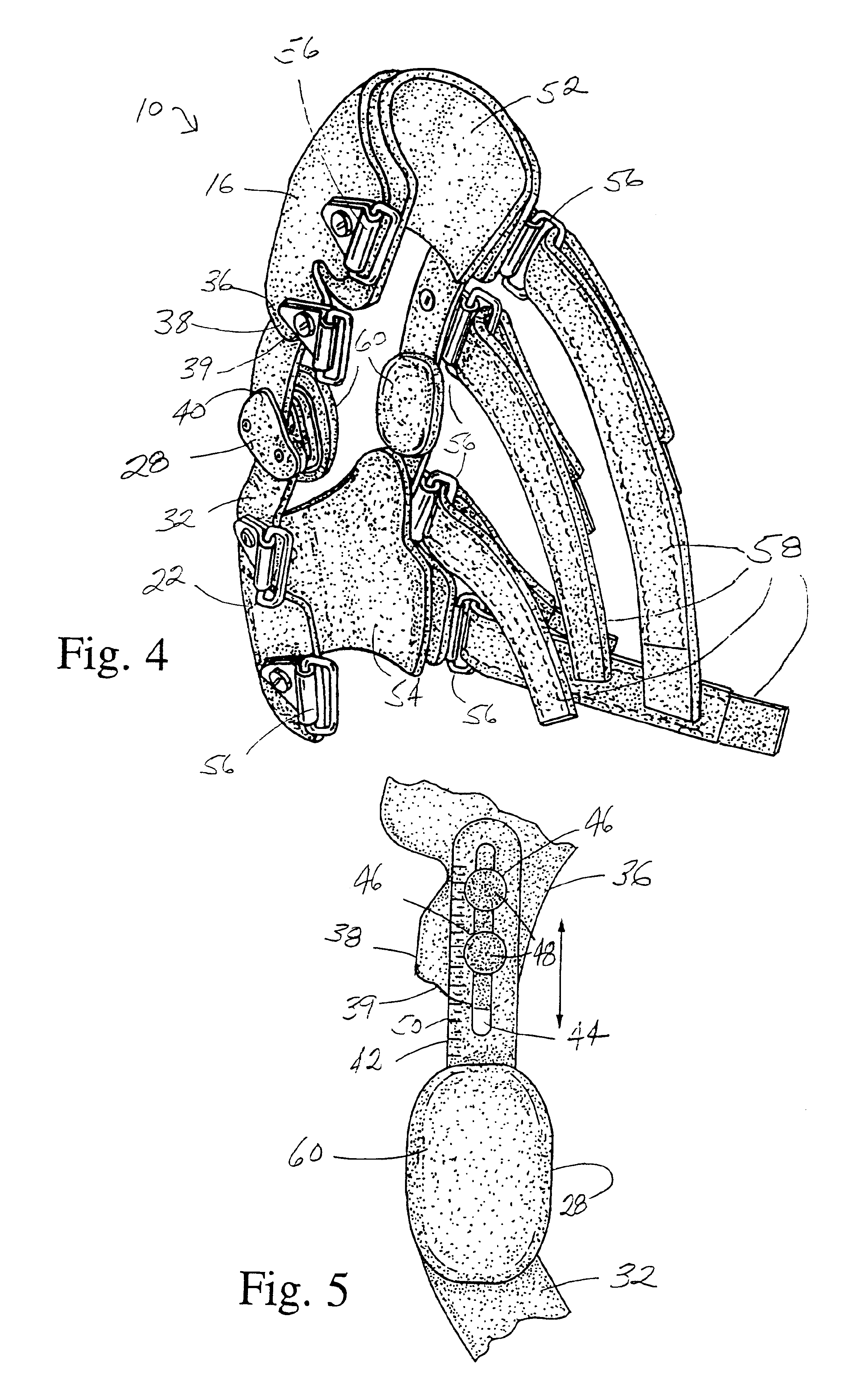
Referring to FIGS. 1-4, a knee brace 10 for supporting a leg 12 of a wearer is illustrated. The brace 10 has an upper member 16 partially surroundingly encompassable about an upper leg portion 18 situated above the knee joint 20 of the wearer, and a lower member 22 partially surroundingly encompassable about a lower leg portion 24 situated below the knee joint 20 of the wearer. A lateral hinge component 26 and a medial hinge component 28 are positionable respectively laterally and medially adjacent the knee joint 20. The lower member 22 has a lateral element 30 and a medial element 32 each extending upwardly and respectively engaged to the lateral hinge component 26 and medial hinge component 28 for extension-flexion movement. The hinge components 26, 28 are ratio swing hinges constructed according to the disclosure in U.S. Pat. No. 4,940,044, incorporated herein in its entirety by reference. These hinge members 26, 28 are thus specifically designed to closely simulate rotational mo...


PUM


Abstract

A knee brace including a lateral hinge component and a medial hinge component, a lower member encompassable about a lower leg portion and having a lateral element and a medical element each extending upwardly and connectingly engaged respectively to the hinge components, an upper member encompassable about an upper leg portion and having a lateral element extending downwardly and connectingly engaged to the lateral hinge component and a medial element extending downwardly to a distal end terminating above the medial hinge component. The distal end has a configuration non-obstructingly complementarity to an upper shape of the medial hinge component for full and uninterrupted flexion of the lower leg at the knee joint. A medially disposed arm is connectingly engaged to the medial hinge component and extends upwardly from the hinge component to be adjacent the medial element of the upper member for connection to each other with a releasably securable slidable engager. The arm and medial element are slidable and securable against each other to thereby laterally inwardly and outwardly position the upper member in angular relationship to the lower member and consequently treat inward or outward leg curvature through correction of knee joint orientation.

Description

STATEMENT RE: FEDERALLY SPONSORED RESEARCH / DEVELOPMENT(Not Applicable)FIELD OF THE INVENTIONThe present invention relates in general to knee braces, and in particular to a knee brace for an osteo-arthritic knee joint wherein non-obstructed full flexion is attainable while laterally inward or outward joint disposition and resulting leg curvature are averted.BACKGROUND OF THE INVENTIONOsteo-arthritis, also known as degenerative joint disease, is the most common form of arthritis and usually occurs after middle age. Especially vulnerable are knee joints where chronic breakdown of cartilage leads to pain, stiffness, and swelling. As the body tries to compensate for this infirmity, the knee joint may migrate laterally or outwardly, or it may migrate inwardly or medially, with the former condition often referred to as “bowlegged” and the latter referred to as “knock-kneed.” When either event occurs, the leg experiences a corresponding curvature, the arthritic condition is not relieved, an...

Claims


Application Information

Patent Timeline
Patent Type & Authority Patents(United States)
IPC IPC(8): A61F5/01
CPCA61F5/0123A61F2005/0174
Inventor CASTILLO, EDWARD L.
Owner OSSUR HF
Learn More