[0019]The present invention has been developed in response to the current state of the art, and in particular, in response to these and other problems and needs that have not been fully or completely solved by currently available non-thermal
plasma generator systems and methods. The present invention effectively resolves at least the problems and shortcomings identified herein. In particular, embodiments of the present invention provide a
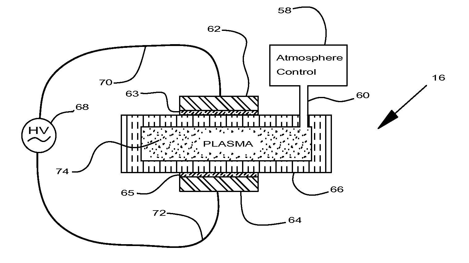
dielectric barrier discharge plasma generator for the treatment of solid surfaces wherein at least a plasma generating
electrode is positioned outside of and separately moveably from a substantially sealed dielectric chamber. The walls of the chamber comprise dielectric material to provide a dielectric barrier positioned between the electrodes and the workpiece. A workpiece is placed or occurs within the dielectric chamber. In various embodiments, the dielectric chamber and the workpiece may be one and the same, or the workpiece may be fully or partially enclosed within the dielectric chamber. A plurality of separate dielectric chambers may be provided. A gap is provided within the dielectric chamber in which non-thermal plasma may form. An atmosphere
control system is provided to control the atmosphere within the chamber. A
transport system is provided for moving the electrodes and the dielectric chamber relative to one another.
Plasma generating electrical power is supplied to the electrode(s). When the
breakdown voltage is achieved in the plasma zone, non-thermal plasma forms. The non-thermal plasma stays in a plasma zone between the electrodes during this relative movement. The solid surfaces that are treated with non-thermal plasma are moved with the dielectric chamber.
Solid surfaces include those that are not fluid. Fluids assume the shape of the container that confines them. Solids are capable of sustaining their own shape. Solids include gels and sols that are capable of sustaining their shapes without support.
Solid surfaces are not limited to surfaces of any particular texture. Woven materials and mats (particularly filters) have solid surfaces, as do particulate and granular materials. Many smooth surfaces are solid, as are many permeable and impermeable surfaces. The
system is particularly adapted to continuous operations, which permits
automation of the process, and the use of non-thermal
plasma treatment in the
mass production of plasma treated solid surfaces, which results in substantial economies of operation. Production rates go up by several orders of magnitude when operations are improved from batch to continuous.
[0024]The use of an elongated workpiece permits long lengths to be treated very quickly. Lengths with aspect ratios (length to internal
diameter) of greater than 100 to 1 may be quickly and conveniently treated with plasma. Lengths of longer workpieces may be selectively treated. For example, if a 100 foot length of treated tubing is desired, and a 1,000 foot long reel of the tubing is available, the entire reel can be quickly evacuated to a pressure of from approximately 1 to 100
Torr, and only the first 100 foot length is treated.
Millimeter sized tubing may be easily treated. Relatively flexible tubes may be treated, because the pressure is not reduced to a level where the tube collapses. Pressures in the millitorr range would collapse many of the tubes that are particularly benefited by this plasma treatment.
[0036]Making the electrodes separable from the dielectric chambers permits the use of multiple dielectric chambers with one set of electrodes. It also substantially reduces the costs of producing both the chambers and the electrodes. Particularly for purposes of
mass production, a large number of interchangeable dielectric chambers can be loaded with workpieces. The atmospheres within each chamber can be adjusted to desired values of pressure and composition before the chamber is mated to a set of electrodes. The pre-prepared dielectric chambers may be placed one by one in plasma treatment association with the electrodes. Conveying such chambers past one or more sets of electrodes at a continuous rate or in a regular stop and go motion permits the
automation of the operation for purposes of
mass production.
[0037]In those embodiments where separate individual chambers are individually loaded with workpieces, the dielectric chambers may be advantageously shaped to accommodate the specific workpieces, and as much as 80 to 90 percent of the volume inside of a particular dielectric chamber is occupied by the workpiece. Such a
void volume of 10 to 20 percent reduces, for example, the load on the
vacuum pump and cycle times, and minimizes the consumption of reagents, if any are employed. The generally separate external electrodes may also be shaped to accommodate the specific chamber-workpiece assemblies. The dielectric chamber walls and the electrodes may be shaped to provide approximately a constant gap between the surface of the workpiece and the electrode. The use of external separate electrodes allows the electrodes to be manufactured inexpensively, as needed, to accommodate different shaped chamber-workpiece assemblies. Cooling may be provided for the electrodes where they are subjected to
continuous use. Typically,
cooling fluid (liquid or gas) is used to cool the electrodes.

