Omnidirectional shadow texture mapping

a shadow texture and cube technology, applied in the field of computer graphics shading, can solve the problems of increasing the amount of processing time needed for rendering, increasing processor time, and reducing performance,

Active Publication Date: 2005-04-05
NVIDIA CORP
View PDF1 Cites 141 Cited by
  • Summary
  • Abstract
  • Description
  • Claims
  • Application Information

AI Technical Summary

Problems solved by technology

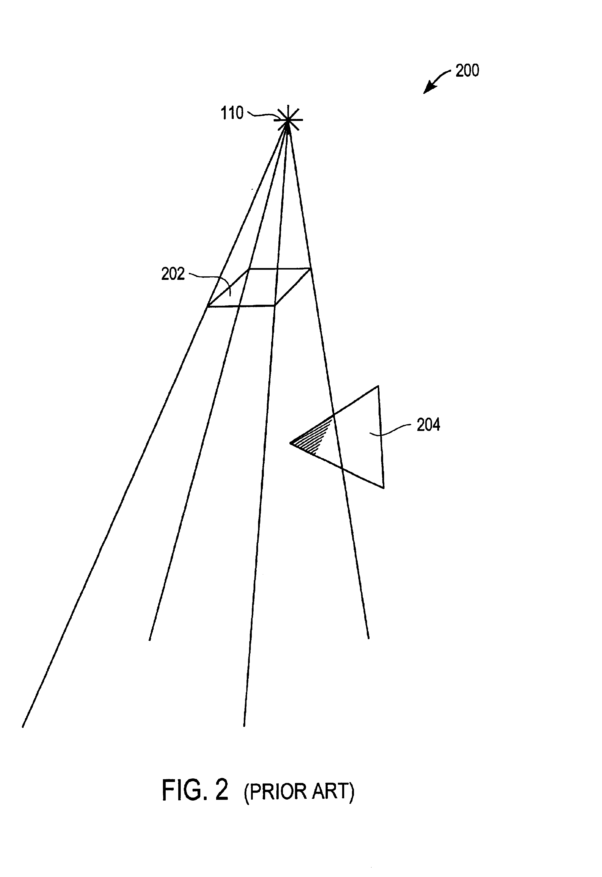
Unfortunately, the construction of each shadow volume space 200 is performed by the central processing unit (CPU) of a computer.
As a result, objects having many curves, and thus many edges, increase the amount of CPU processing time needed for rendering.
Although shadow texturing works well for light sources that are essentially spotlights that cast shadows in one directio...

Method used


Image

  • Omnidirectional shadow texture mapping
  • Omnidirectional shadow texture mapping
  • Omnidirectional shadow texture mapping

Examples


Embodiment Construction

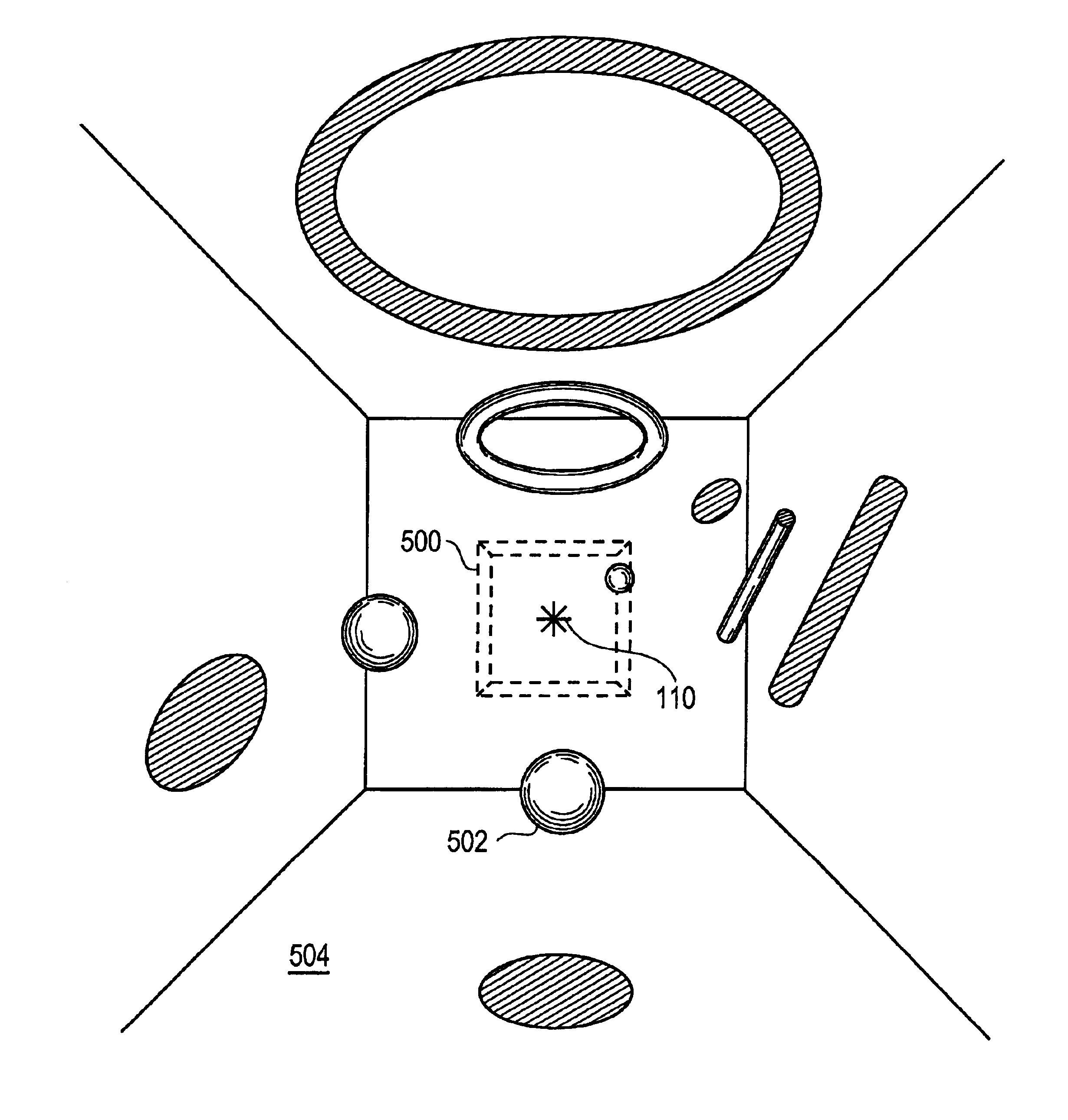
An invention is disclosed for omnidirectional shadow texture mapping via a shadow cube texture map. Using the shadow cube texture map, embodiments of the present invention allow omnidirectional shading using a single texture lookup. In the following description, numerous specific details are set forth in order to provide a thorough understanding of the present invention. It will be apparent, however, to one skilled in the art that the present invention may be practiced without some or all of these specific details. In other instances, well known process steps have not been described in detail in order not to unnecessarily obscure the present invention.

Broadly speaking, the embodiments of the present invention provide an enhanced form of Cube Texture Mapping which transforms a three dimensional vector (representing a light-to-surface vector) into a Cube Face Identifier (selecting one of six cube face two dimensional texture maps), a two dimensional texture coordinate (selecting a par...


PUM


Abstract

An invention is provided for rendering using an omnidirectional light. A shadow cube texture map having six cube faces centered by a light source is generated. Each cube face comprises a shadow texture having depth data from a perspective of the light source. In addition, each cube face is associated with an axis of a three-dimensional coordinate system. For each object fragment rendered from the camera's perspective a light-to-surface vector is defined from the light source to the object fragment, and particular texels within particular cube faces are selected based on the light-to-surface vector. The texel values are tested against a depth value computed from the light to surface vector. The object fragment is textured as in light or shadow according to the outcome of the test.

Description

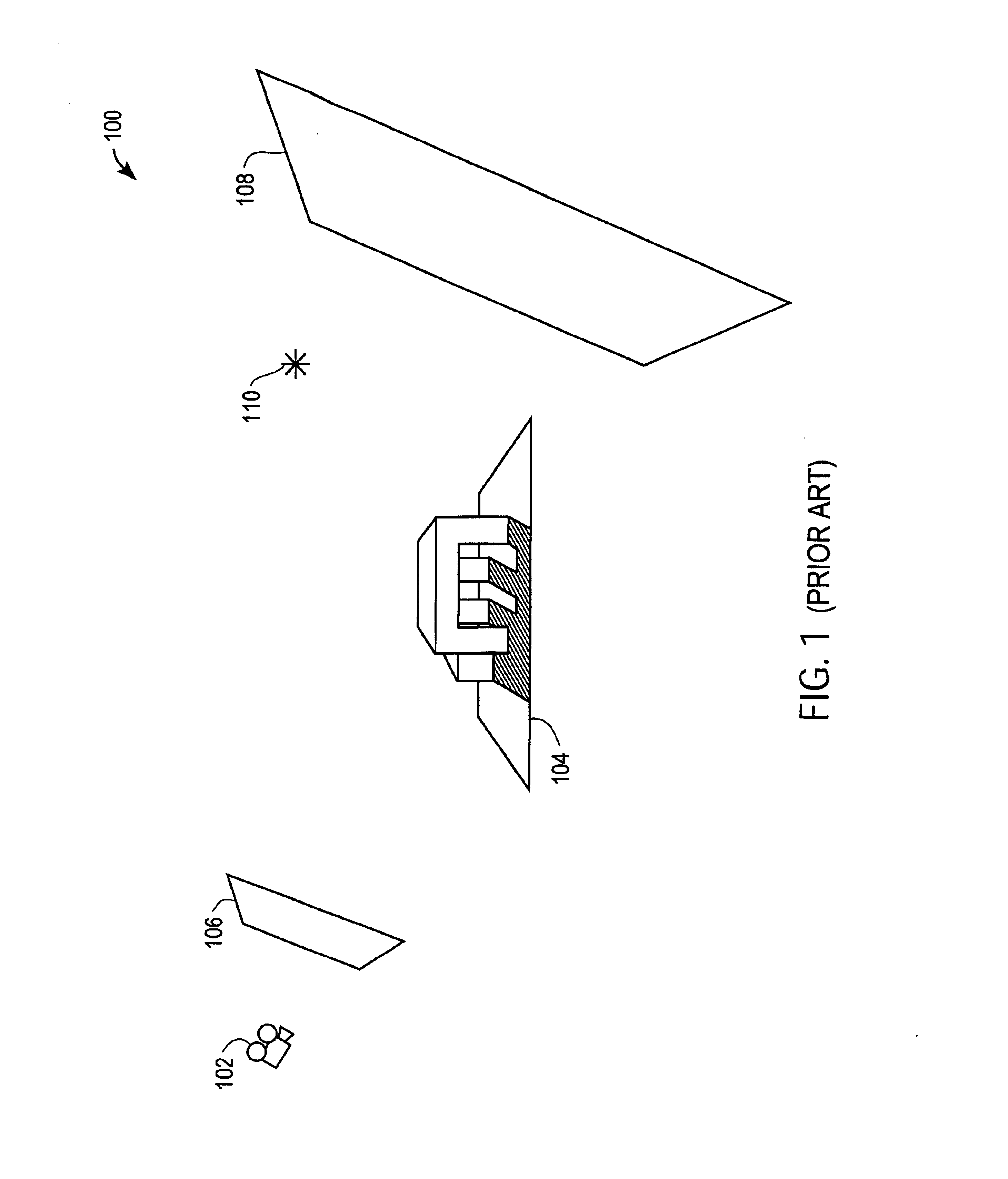
BACKGROUND OF THE INVENTION1. Field of the InventionThe present invention relates generally to computer graphics shading and more specifically to omnidirectional shading using a shadow texture cube mapping.2. Description of the Related ArtReal-time computer image systems are designed to provide realistic image reproduction for a wide variety of graphics systems, such as flight simulators, action games, and engineering workstations. For example, graphics-based simulators can be used as training devices, which permit combatants to obtain practice without the necessity of going out into the field and using the actual combat systems. The simulators enable a user, such as a pilot, to maintain and improve their skills without the cost associated with live training. As such, it is advantageous to provide the user with video display realism.FIG. 1 is a diagram showing a three-dimensional (3D) viewing space 100. When creating three-dimensional computer generated graphics, 3D objects 104 are ...

Claims


Application Information

Patent Timeline
IPC IPC(8): G06T15/00G06T15/04G06T15/60
CPCG06T15/04G06T15/60G06T2215/12
Inventor NEWHALL, JR., WILLIAM P.KILGARD, MARK J.
Owner NVIDIA CORP
Why Eureka
Try Eureka