Electric projection screen roller and balance rod assembly

a technology of projection screen and roller, which is applied in the direction of door/window protective devices, instruments, shutters/movable grilles, etc., can solve the problems of wasting time, troublesome replacement of new paperboard, and affecting the service life of the projection screen, so as to prolong the service life and facilitate assembly or disassembly.

Inactive Publication Date: 2005-04-05
LIN HSIN FU
View PDF4 Cites 41 Cited by
  • Summary
  • Abstract
  • Description
  • Claims
  • Application Information

AI Technical Summary

Benefits of technology

An object of the present invention is to provide an electric projection screen roller and balance rod assembly which can be easily assembled or disassembled.
Another object of the present invention is to provide an electric projection screen roller and balance

Problems solved by technology

It is troublesome to replace new paperboard.5. It is troublesome and wastes time for the lower end section 201 of the projection screen 20 to be clamped by pieces of paperboard

Method used


Image

  • Electric projection screen roller and balance rod assembly
  • Electric projection screen roller and balance rod assembly
  • Electric projection screen roller and balance rod assembly

Examples


Embodiment Construction

An preferred embodiment of the electric projection screen roller and balance rod assembly in the present invention includes a projection screen roller assembly and a projection screen balance rod assembly.

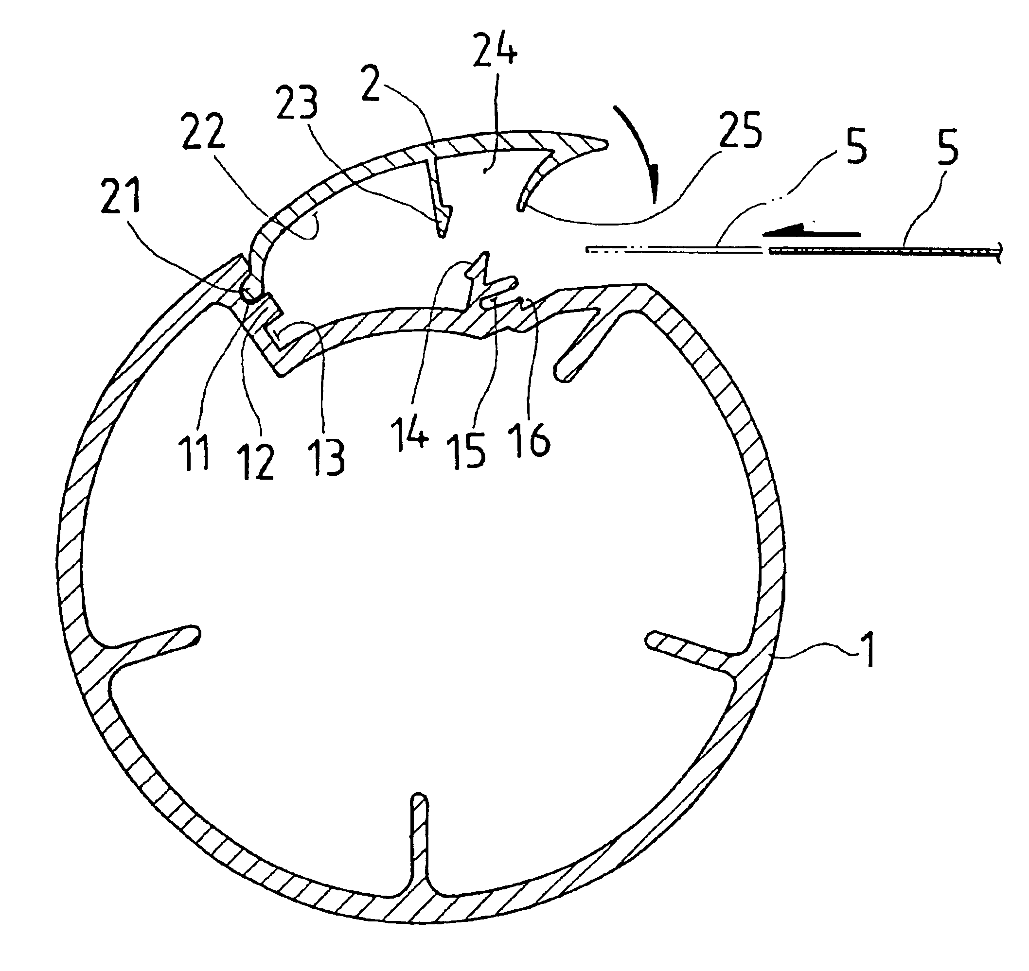
Referring to FIG. 7, the projection screen roller assembly is composed by a main body 1 and an inserting piece 2. The main body 1 is provided with a groove 11 in one predetermined position of the upper facing surface, a flanged strip 12 is provided adjacent to the groove 11, a hollow 13 is provided adjacent to the flanged strip 12, a slant against block 14 is provided at one predetermined position on the upper facing surface of the main body 1, a recess 15 is provided at one side of the slant against block 14, and the characteristic lies in that an inlaying socket 16 is provided adjacent to the recess 15.

The inserting piece 2 is provided with a flange 21 at one side, a hollow 22 is formed adjacent to the flange 21, a hook block 23 is provided adjacent to the hollow 22, another holl...


PUM


Abstract

An electric projection screen roller and balance rod assembly. The electric projection screen roller and balance rod assembly includes a projection screen roler assembly and a balance rod assembly. The projection screen roler assembly is composed by a main body and an inserting piece, and the projection screen balance rod assembly is composed by a left half portion and a right half portion. A curved against member of the inserting piece is provided to be caught in the inlaying socket of the main body, so as for the upper end section of a projection screen to be firmly secured between, and the lower end section of the projection screen is firmly secured between the left and right half portions of the projection screen balance rod.

Description

BACKGROUND OF THE INVENTION1. Field of the InventionThe present invention relates to an electric projection screen roller and balance rod assembly. More particularly, the present invention is directed to an electric projection screen roller and balance rod assembly that is provided in a protective housing and included a screen roller assembly and a screen balance rod assembly, so as for the upper end section of a projection screen to be firmly secured to the roller assembly and the lower end section of the projection screen to be firmly secured to the balance rod assembly.2. Description of the Related ArtVarious activities to pass on knowledge and information are frequently held in modern times. Projectors are widely used as auxiliary teaching tools in most teaching activities. Accordingly, a projection screen is indispensable for showing the projected content from the a projector.While being used, referring to FIGS. 1,2 and 3, an electric projection screen housing 10 containing a s...

Claims


Application Information

Patent Timeline
IPC IPC(8): E06B9/24E06B9/40G03B21/56G03B21/58
CPCE06B9/40G03B21/58Y10S160/10Y10S160/903
Inventor LIN, HSIN-FU
Owner LIN HSIN FU
Why Eureka
Try Eureka