Monitoring activity of a user in locomotion on foot

a technology for locomotion and activity monitoring, applied in the direction of electric unknown time interval measurement, speed/acceleration/shock instrument details, setting time indication, etc., can solve the problems of high impact environment, frequent failure, and inaccurate foot contact time (tc) measuremen

Inactive Publication Date: 2005-04-05
NIKE INC +1
View PDF56 Cites 696 Cited by
  • Summary
  • Abstract
  • Description
  • Claims
  • Application Information

AI Technical Summary

Benefits of technology

According to one aspect of the present invention, a method involves determining at least one calculated parameter based upon at least one determined performance parameter of the user and at least one determined variable physiological parameter of the user.

Problems solved by technology

These sensors, however, are subjected to a high-impact environment inside of the shoe, and therefore fail frequently.
In addition, inaccurate foot contact time (Tc) measurements may result when a user is taking strides during which either the heel sensor or the toe sensor is not activated, for example, when a user is running on his or her toes.
These “weight-on-a-spring” pedometers, however, generally cannot measure the distance traveled by a runner because the weight experiences excessive bouncing during running and footsteps are often “double-counted” because of this bouncing, thereby causing the pedometer to produce inaccurate results.
These devices therefore cannot be used across different training regimes (e.g., walking, jogging, and running).
Thus, these accelerometer-based devices are subject to similar limitations as are the weight-on-a-spring devices, and are not capable of measuring the foot contact time (Tc) of a user in locomotion.

Method used


Image

  • Monitoring activity of a user in locomotion on foot
  • Monitoring activity of a user in locomotion on foot
  • Monitoring activity of a user in locomotion on foot

Examples


Embodiment Construction

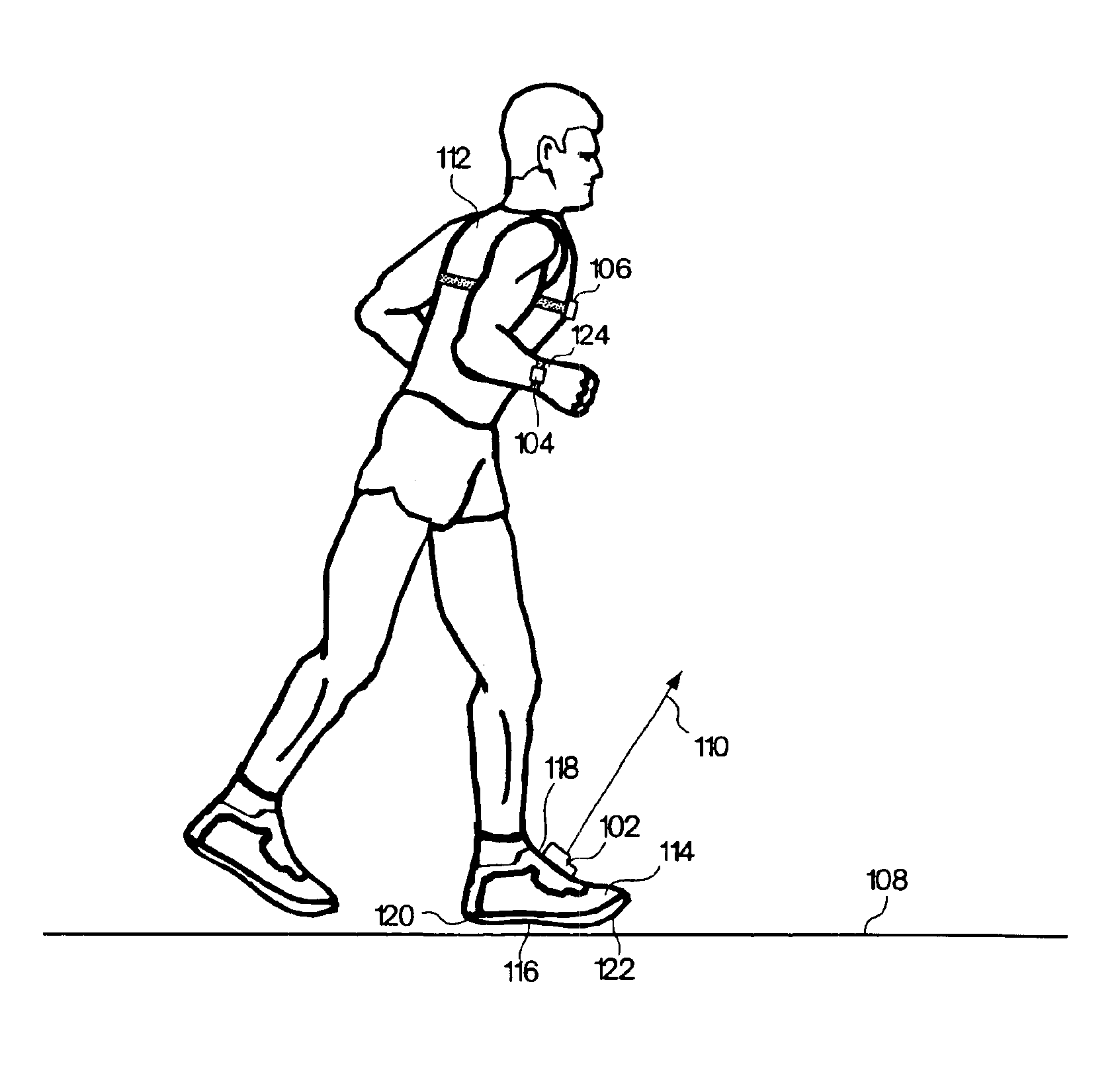
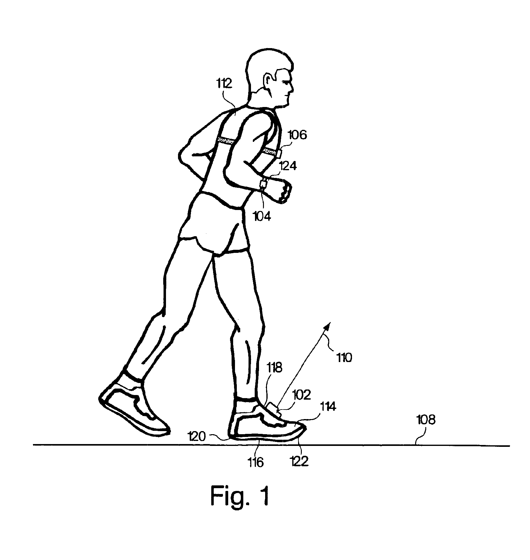
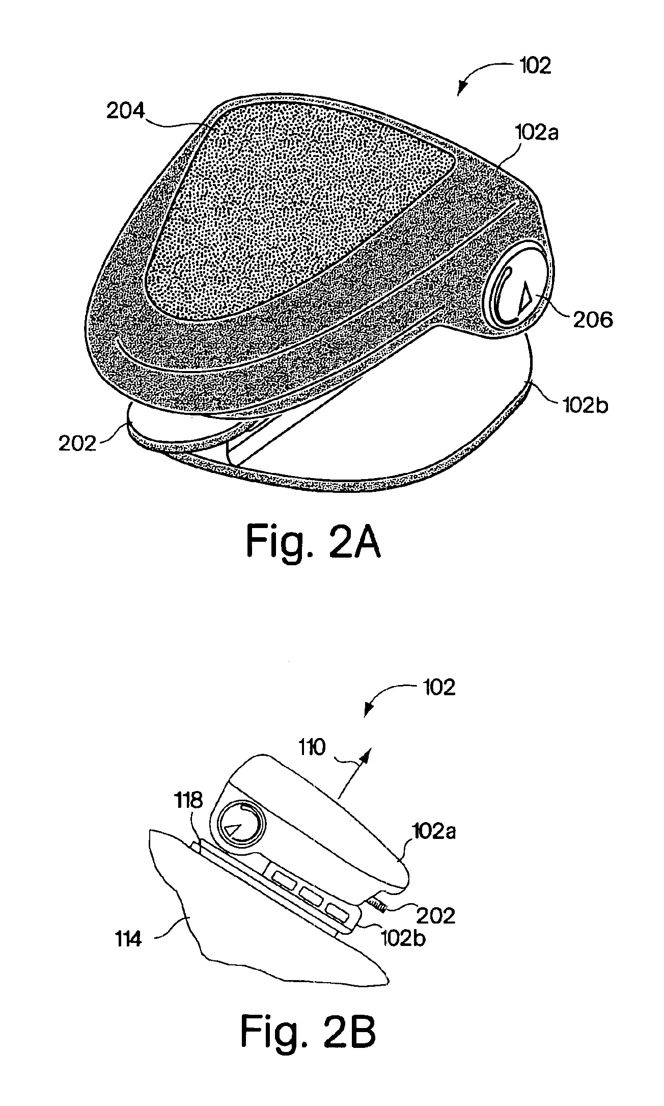
An illustrative embodiment of a system for monitoring activity of a user in locomotion is shown in FIG. 1. As shown, the system includes a foot-mounted unit 102, a wrist-mounted unit 104, and a chest-mounted unit 106, all attached to a user 112 who is in locomotion (i.e., walking or running) on a surface 108. In accordance with one aspect of the present invention, the foot-mounted unit 102 includes a sensor for sensing motion of a foot 114 of the user 112.

The sensor included in the foot-mounted unit 102 may be any of a number of devices capable of sensing the motion of the user's foot 114, and the invention is not limited to the use of any particular type of sensor. In one illustrative embodiment, for example, the foot-mounted unit 102 includes a solid-state accelerometer that senses acceleration along an acceleration sensing axis 10, as shown in FIG. 1. In another embodiment, the sensor includes a low-cost accelerometer such as that disclosed in co-pending patent application Ser. N...


PUM


Abstract

In one embodiment, a method includes steps of: (a) identifying an average foot contact time of a user during a first outing; (b) identifying an average pace of the user during the first outing; (c) defining a relationship between foot contact times of the user and corresponding paces of the user, wherein the relationship is based upon the average foot contact time and the average pace identified during the first outing, and wherein no other average foot contact times and no other average paces identified during any different outings by the user are used to define the relationship; and (d) calibrating at least one device that monitors activity of the user in locomotion on foot based upon the defined relationship between foot contact times of the user and corresponding paces of the user. In another embodiment, a method includes steps of: (a) determining a single user-specific calibration constant that defines a relationship between foot contact times of a user and corresponding paces of the user, wherein no other user-specific calibration constants are used to define the relationship; and (b) calibrating at least one device that monitors activity of the user in locomotion on foot based upon the relationship between foot contact times of the user and corresponding paces of the user that is defined by the single user-specific calibration constant.

Description

BACKGROUND OF THE INVENTION1. Field of the InventionThe present invention relates to the monitoring of the activity of a user in locomotion on foot.2. Discussion of the Related ArtIt is known that useful information may be derived from the measurement of the “foot contact time” (Tc) of a user in locomotion, wherein “foot contact time” refers to the period of time that a foot of a user is in contact with the surface during a stride taken by the user while the user is in locomotion on foot. Once the foot contact time (Tc) of the user is known, other information, such as rate of travel, distance traveled, and ambulatory expended energy may be calculated based upon this measured foot contact time (Tc).In the past, foot contact time (Tc) has been measured by placing pressure-sensitive sensors or switches, such as resistive sensors, in both the heel and toe portions of the sole of a shoe, and measuring a time difference between a first signal output by the heel sensor (which indicates tha...

Claims


Application Information

Patent Timeline
Patent Type & Authority Patents(United States)
IPC IPC(8): A43B23/24A43B23/00A61B5/103G01P15/08G01P1/02G01C22/00G01P15/09G01P1/00G04G1/00G04G1/04G04G21/02G16H20/30
CPCA43B3/0005A61B5/742A43B3/0078A43B23/24A61B5/1038A61B5/681A61B5/6831A63B69/0028G01C22/006G01P1/023G01P15/08G01P15/0922G04G21/025A61B5/1118A61B5/112A61B5/7278A43B3/0031A63B2024/0065A63B2220/17A63B2225/02G01N2291/02827G06F19/3481A61B5/6895A61B5/02438A61B5/6807A61B2503/10A61B2560/0223G16H20/30A43B3/34A61B5/0205A61B5/1112A61B5/486A61B5/4866A61B5/7246A61B5/725A61B5/743A61B5/7475A61B2562/0219A61B2562/08
Inventor DARLEY, JESSEOHLENBUSCH, NORBERT
Owner NIKE INC
Why Eureka
Try Eureka