
Motion track determination method, device and system

A technology of motion trajectory and determination method, which is applied in the direction of measuring devices, measuring distances, instruments, etc., can solve the problems of threatening the life safety of firefighters, negative impact, and being unable to record their surrounding environment, and achieve the goal of improving accuracy and stability Effect

Pending Publication Date: 2022-05-13
THE UNIV OF NOTTINGHAM NINGBO CHINA +1
View PDF0 Cites 0 Cited by
  • Summary
  • Abstract
  • Description
  • Claims
  • Application Information

AI Technical Summary

Problems solved by technology

However, during indoor rescue work, firefighters are unable to know the current location information of themselves and their teammates, and cannot record the routes they have traveled and the surrounding environment due to problems such as visibility, wireless communication signal connection restrictions, and GPS signal communication obstruction. It can only abstractly describe the surrounding building structure and location through walkie-talkies. In an emergency, the lack of effective positioning means will threaten the life safety of firefighters. great resistance
[0003] In the prior art, the attitude estimation algorithm based on the inertial sensor can use the inertial data of the wearer to estimate the position information during the movement. However, this type of algorithm is not accurate enough in the calculation of steps detection and step length, and in the step direction estimation. It is easy to have significant cumulative drift errors due to differences in the wearer's gait habits. In complex indoor rescue environments, the cumulative errors will largely interfere with position judgment and even bring negative effects

Method used


Image

  • Motion track determination method, device and system
  • Motion track determination method, device and system
  • Motion track determination method, device and system

Examples


Embodiment 1

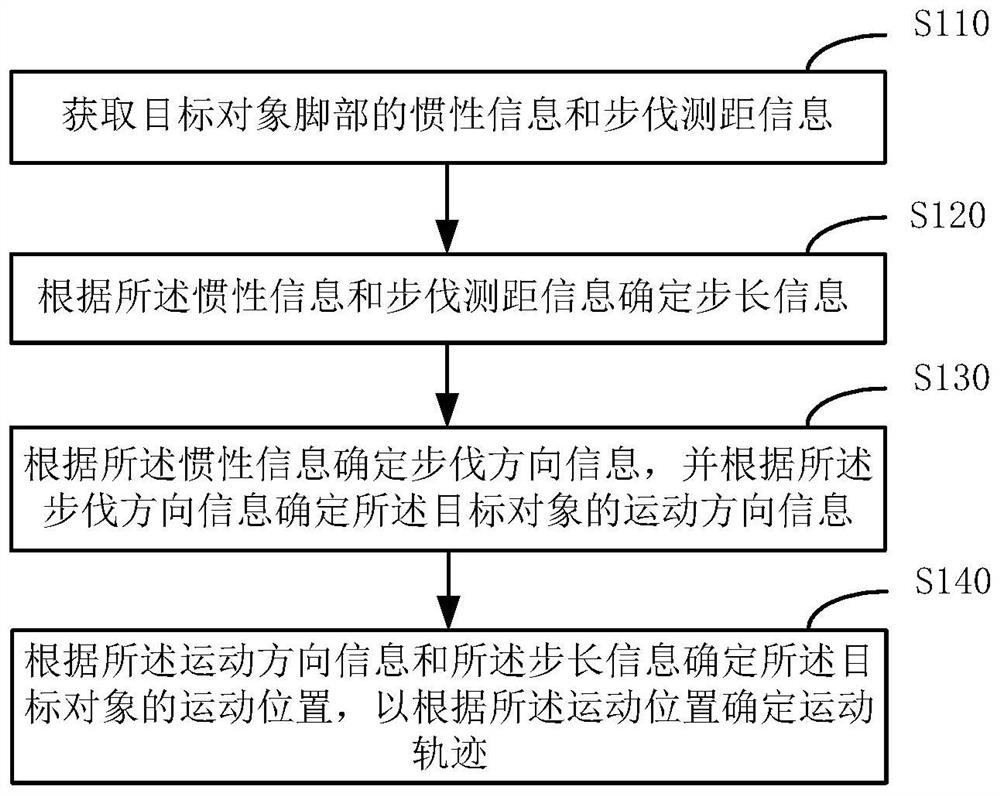
[0030] figure 1 It is a flowchart of a method for determining a motion trajectory provided by Embodiment 1 of the present invention. This embodiment is applicable to the situation of determining the motion trajectory of a target object indoors. This method can be implemented by the device for determining the motion trajectory provided by the embodiment of the present invention. Execution, the device may be implemented by software and / or hardware. see figure 1 , the method for determining the motion trajectory provided by this embodiment includes:

[0031] S110. Acquire inertial information and step distance measurement information of the target object's feet.

[0032] Among them, the target object is the object that needs to obtain positioning information; the inertial information and step distance measurement information of the target object's feet can be obtained through different sensors set on the target object's feet, such as firefighters' fire protection boots , for e...

Embodiment 2

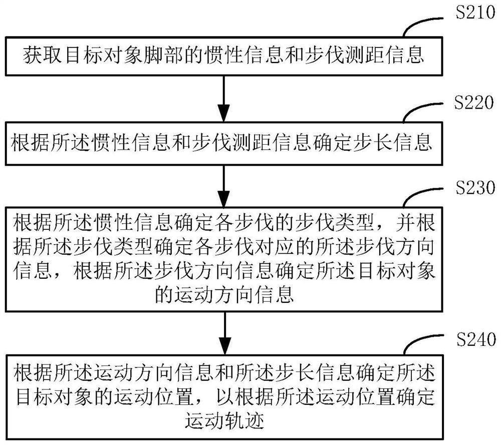
[0056] figure 2 It is a flow chart of a method for determining a motion trajectory provided by Embodiment 2 of the present invention. This technical solution is a supplementary explanation for the process of determining step direction information based on the inertial information. Compared with the above scheme, the specific optimization of this scheme is to determine the step direction information according to the inertial information, including:

[0057] The step type of each step is determined according to the inertial information, and the step direction information corresponding to each step is determined according to the step type. Specifically, the flow chart of the method for determining the motion trajectory is as follows: figure 2 Shown:

[0058] S210. Acquire inertial information and step distance measurement information of the target object's feet.

[0059] S220. Determine step size information according to the inertial information and step ranging information....

Embodiment 3

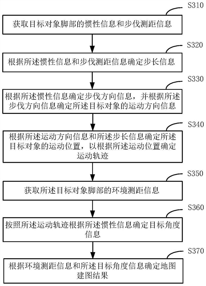
[0078] image 3 It is a flow chart of a method for determining a motion trajectory provided by Embodiment 3 of the present invention, and this technical solution is a supplementary explanation for the mapping process. Compared with the above scheme, the specific optimization of this scheme also includes:

[0079] Acquiring environmental ranging information of the target object's feet;

[0080] determining target angle information according to the motion trajectory according to the inertial information;

[0081] A map construction result is determined according to the environmental ranging information and the target angle information. The flow chart of the specific motion trajectory determination method is as follows: image 3 Shown:

[0082] S310. Acquire inertial information and step distance measurement information of the target object's feet.

[0083] S320. Determine step length information according to the inertial information and step ranging information.

[0084] S...


PUM


Abstract

The invention discloses a motion trail determination method, device and system. The method comprises the following steps: acquiring inertia information and pace distance measurement information of a foot of a target object; step length information is determined according to the inertia information and the step distance measurement information; step direction information is determined according to the inertia information, and motion direction information of the target object is determined according to the step direction information; and determining a motion position of the target object according to the motion direction information and the step length information, so as to determine a motion track according to the motion position. Through operation of the technical scheme provided by the embodiment of the invention, the problems of interference on position judgment and negative effects caused by obvious accumulated drift errors in direction estimation in the prior art can be solved, and the beneficial effect of improving the positioning accuracy and stability is achieved.

Description

technical field [0001] The present invention relates to positioning technology, in particular to a method, device and system for determining a motion track. Background technique [0002] In recent years, with the acceleration of urbanization, the number of large-scale buildings with complex indoor structures such as commercial complex buildings, large residential apartments, and large-scale industrial plant parks has increased. Although the huge building area and fine indoor functional zoning provide more citizens with production and living space needs, it also brings many potential hidden dangers to the field of fire safety. As the main force of fire rescue work, firefighters need to adopt teamwork and work together in the rescue process to achieve efficient rescue. However, during indoor rescue work, firefighters are unable to know the current location information of themselves and their teammates, and cannot record the routes they have traveled and the surrounding enviro...

Claims


Application Information

Patent Timeline
IPC IPC(8): G01C21/16G01C22/00G01C23/00
CPCG01C21/165G01C21/1652G01C22/006G01C23/00
Inventor 李汶锦吴仁杰马舒克柴晓卿
Owner THE UNIV OF NOTTINGHAM NINGBO CHINA
Learn More