
Open frame tray clip

a technology for securing trays and trays, applied in the field of open frame clips, can solve the problems of permanent warp/distortion of trays, damage to components, gaps between trays in stacks, etc., and achieve the effect of reducing warp

Inactive Publication Date: 2005-04-12
PEAK PLASTIC & METAL PRODS INT
View PDF5 Cites 8 Cited by
  • Summary
  • Abstract
  • Description
  • Claims
  • Application Information

AI Technical Summary

Benefits of technology

"The invention provides a clip for securing a stack of trays that minimizes warp due to tray clip forces. The clip has a base with a cut-away relief area for finger access and first and second resilient side walls and a back wall that apply pressure to the tray edges, reducing leverage to the stack and minimizing tray warpage. The technical effect is an improved clip for securing a stack of trays that reduces warp and damage to the trays during transportation."

Problems solved by technology

Prior art designs apply force to a central area of the bottom of the stack, which eventually causes permanent warp / distortion of the trays.
This force causes damage due to the application of the force in the thin and weak central area.
As the trays warp over time, gaps are produced between trays in a stack.
In some cases, the components stored in a tray can-fall through the gaps, or be pinched ir) a gap, causing damage to the component.
In addition, when a stack of trays is removed from a clip, and a tray is presented to an automated pick and place machine, the warped, distorted tray can cause pick-up errors.
A disadvantage of this design includes the pressure of the springs 46 located within the more fragile central area of the trays, and the limited openings 42 and 44 which obscure the view of the tray labels.
Also, the springs 46 do not allow enough motion to properly accommodate stacks of trays with minimum or maximum tolerances.

Method used


Image

  • Open frame tray clip
  • Open frame tray clip
  • Open frame tray clip

Examples


Embodiment Construction

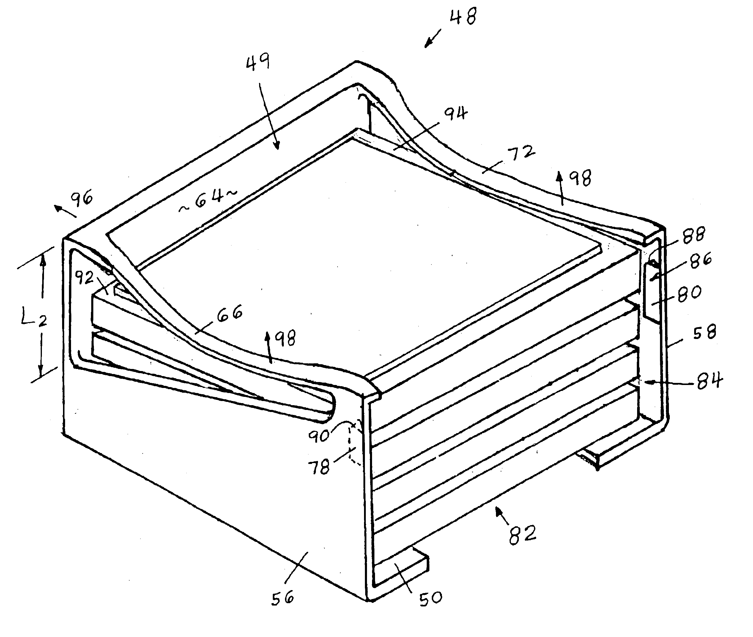
Referring now to FIG. 6 of the drawing, an open frame clip 48 according to the present invention is shown in a perspective view. The clip 48 is configured for storing a stack of trays, or trays and a tray cover in a chamber-49. The clip 48 housing has a base 50 with a tray storing area of width “W” and depth “D”. The base 50 has a cut-out 52 extending inward from a front edge 54 of the base 50 allowing access for an operator's finger for gripping the bottom of a stack of trays. First and second sidewalls 56 and 58, constructed of resilient material extend at substantially right angles to the base 50 from opposing first and second base edges 60 and 62. The top 51 and front tray entry 53 are notably open, facilitating operator installation and removal of a tray stack, and allowing a clear view Of stack labeling. The side walls 56 and 58 are unsupported on at least two edges having no connection between them on the upper edges 55 and 57 and front edges 59 and 61. A back wall 64, also c...


PUM


Abstract

A clip is provided for holding a stack of trays and a tray cover. The clip has a base having a width providing clearance for a width of a tray and a cut-away relief area for finger access. First and second opposing resilient side walls and a resilient back wall extend upward from the base, forming a structure with an open front and top. First and second resilient, elongated and downwardly curved members are included, each having a proximal end attached to an upper front of a corresponding side wall, and a distal end attached to the back wall. The resilient members are positioned so as to apply pressure to first and second opposing perimeter portions of a tray placed in the clip.

Description

BACKGROUND OF THE INVENTION1. Field of the InventionThis application is related to U.S. patent application Ser. No. 10 / 620,282 entitled “Bare Die fray Clip” filed the same day as this application, and which is expressly 2incorporated by reference herein.This invention relates generally to apparatus for securing trays that are used in storing or transporting components such as semiconductors, and more particularly to an open frame clip for securing a stack of trays and a cover that places stack compression forces on tray perimeters for accommodating large tolerances in stack heights, and provides a clear view of a tray label and improved clearance for operator access to insert and remove a stack.2. Description of the Prior ArtSmall components such as semiconductors are often stored or shipped in molded plastic trays such as tray 10 shown in FIG. 1. With the components (not shown) in pockets 12, a cover such as cover 14 is placed over the tray 10 for captivating the components in the ...

Claims


Application Information

Patent Timeline
Patent Type & Authority Patents(United States)
IPC IPC(8): H05K13/00B65D21/02B65D85/38B65D85/86
CPCH05K13/0084Y10T24/44983
Inventor BRADLEY, SCOTT C.PYLANT, JAMES D.
Owner PEAK PLASTIC & METAL PRODS INT
Learn More