Bare die tray clip

a technology for securing trays and dies, applied in the direction of snap fasteners, packaged goods types, instruments, etc., can solve the problems of warp, gap between trays in stacks, permanent damage to trays, etc., and achieve the effect of reducing warp

Inactive Publication Date: 2006-11-09
PEAK PLASTIC & METAL PRODS INT
View PDF11 Cites 1 Cited by
  • Summary
  • Abstract
  • Description
  • Claims
  • Application Information

AI Technical Summary

Benefits of technology

[0008] It is an advantage of this invention in that it provides an improved clip for securing a stack of trays that minimizes warp due to tray clip forces.
[0009] It is a further advantage of this invention in that it provides a clip for securing a stack of trays that confines the retaining forces to the tray edges and therefore minimizes leverage to the stack and reduces tray warpage.

Problems solved by technology

Prior art designs apply force to a central area of the bottom of the stack, which eventually causes permanent damage to the trays.
This force causes damage due to the application of the force in the thin and weak central area.
As the trays warp over time, gaps are produced between trays in a stack.
In some cases, the components stored in a tray can fall through the gaps, or be pinched in a gap, causing damage to the component.
In addition, when a stack of trays is removed from a clip, and a tray is presented to an automated pick and place machine, the warped, distorted tray can cause pick-up errors.
The problem of warped trays is augmented in situations when trays are recycled i.e. re-used after having been used in a stack and become warped.
For example, if a used warped tray is placed in a stack with a new tray or new cover, significant gaps are possible, causing tray components to fall out.
Stack compressive forces applied by the clip are substantially limited to tray and cover perimeter rail portions.

Method used


Image

  • Bare die tray clip
  • Bare die tray clip
  • Bare die tray clip

Examples


Embodiment Construction

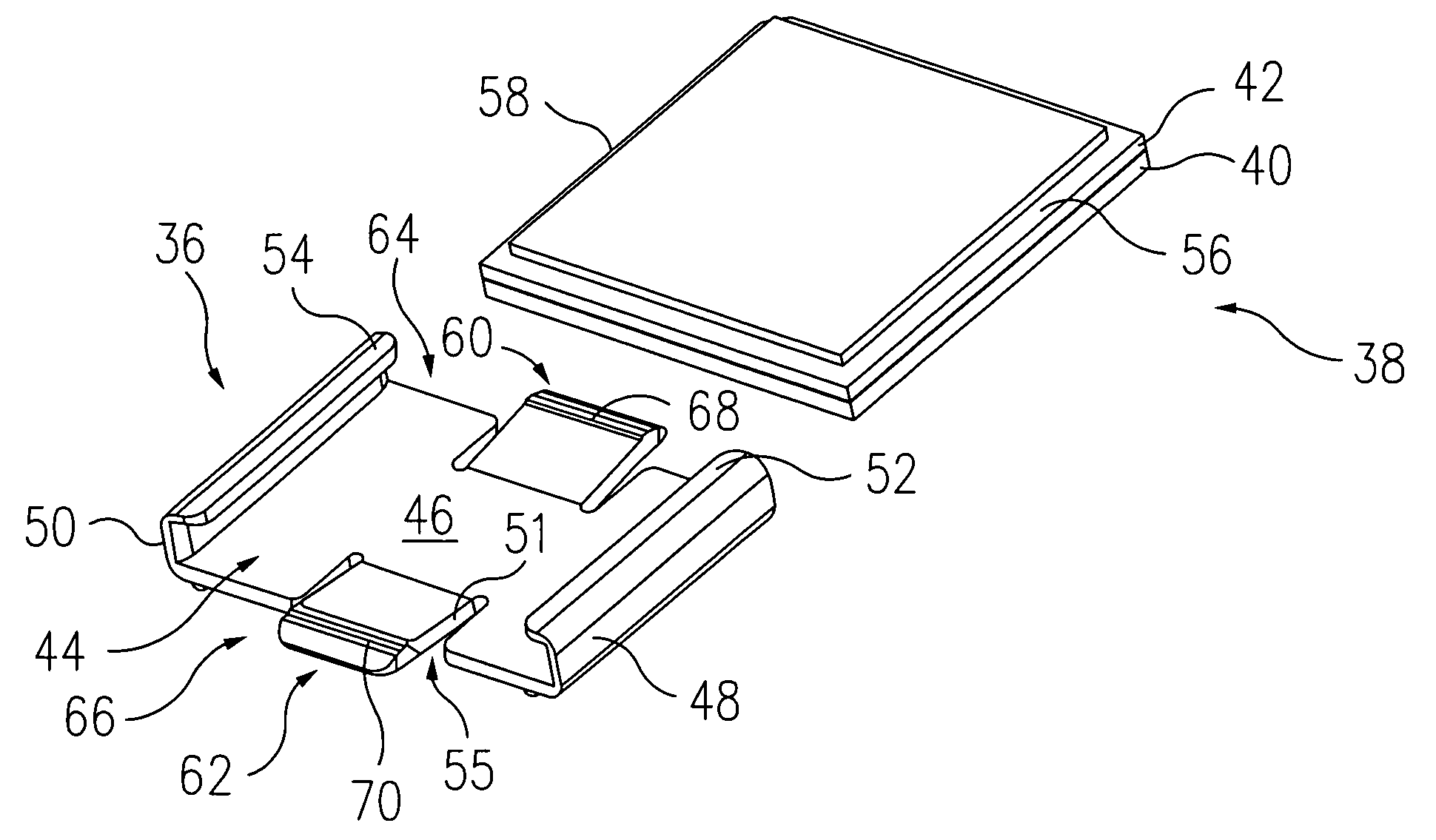
[0023] Referring now to FIG. 5 of the drawings, a particular embodiment of the present invention is shown in the form of a clip 36 for holding a stack, such as stack 38 including a tray 40 and cover 42. The clip 36 forms a channel structure providing a channel 44. The structure includes a clip base 46, and has first and second restraining segments 48 and 50 that can be of various forms, illustrated in FIG. 5 as vertically oriented walls providing left and right captivation of a stack. The restraining segments and base restrict lateral and vertical movement of a stack of trays placed in the channel. Vertical captivation of a stack in the particular embodiment of FIG. 5 is provided in the upward direction by right side and left side protrusions 52 and 54, positioned above a channel base 46, and inwardly directed towards a central area of the channel 44 from left and right side restraining segments 48 and 50 respectively. The protrusions 52 and 54 are positioned above the base 46 so as...


PUM


Abstract

A clip is provided for holding a stack of at least one tray and tray cover. Stack compressive forces applied by the clip are substantially limited to tray and cover edge portions. The clip has a channel base with left and right side walls attached for restricting movement of a stack in left and right directions. Protrusions above the base extend inward towards the walls of the channel for captivating the stack in an upward direction. Spring protrusions extend upward from the base on input and output ends of the channel, and are configured for applying an upward spring force on opposing bottom edge areas of the stack.

Description

BACKGROUND OF THE INVENTION [0001] 1. Field of the Invention [0002] This application is a divisional of Ser. No. 10 / 620,282, which is currently pending and assigned to the Assignee of the present application. This application is also related to U.S. Pat. No. 6,877,194 entitled “Open Frame Tray Clip” filed on Jul. 14, 2003, which is expressly incorporated by reference herein. [0003] This invention relates generally to apparatus for securing trays that are used in storing or transporting components such as semiconductors, and more particularly to a clip for securing a tray and cover or stack of trays and a cover that places stack compression forces on tray perimeter rails in order to minimize tray distortion caused by clip forces. [0004] 2. Description of the Prior Art [0005] Small components such as semiconductors are often stored or shipped in molded plastic trays such as tray 10 shown in FIG. 1. With the components (not shown) in pockets 12, a cover such as cover 14 is placed over ...

Claims


Application Information

Patent Timeline
Patent Type & Authority Applications(United States)
IPC IPC(8): A44B21/00B65D67/02A44B99/00B65D45/16B65D85/86H01L21/673
CPCY10T24/44983H01L21/67333
Inventor PYLANT, JAMES D.BRADLEY, SCOTT C.WABER, ALAN
Owner PEAK PLASTIC & METAL PRODS INT
Why Eureka
Try Eureka