Method and apparatus for directional and controlled cooling in vacuum furnaces

Inactive Publication Date: 2007-02-22
G T ENTERPRISES
View PDF15 Cites 0 Cited by
  • Summary
  • Abstract
  • Description
  • Claims
  • Application Information

AI Technical Summary

Benefits of technology

[0006] The present invention, in one aspect, comprises a cooling vacuum furnace where there is an external gas cooling arrangement and a design that divides the internal chamber of the plenum into a plurality of non-circumferential sectors. This design provides different levels of cooling to different areas of the load so as to minimize warping. Specifically, the plenum may, in one embodiment, comprise both an inner and an outer wall, the outer wall being connected to secondary piping manifolds from which inert gas is supplied and the inner wall having a plurality of gas nozzles, such as threaded tank flanges as in the preferred embodiment. The plenum may further compri

Problems solved by technology

Both approaches work; however, the internal type of cooling arrangement tends to require higher and more frequent maintenance due to the proximity of the moving parts to the heated areas.
Further, many loads being cooled in such furnaces are not uniform in density or mass.
As a result, the uniform cooling provided by traditional furnaces causes certain portions of the load to cool at a higher rate resulting in warping or other damage to the load.
These baffles are, however, directly exposed to the heat inside the furnace.
As such, t

Method used


Image

  • Method and apparatus for directional and controlled cooling in vacuum furnaces
  • Method and apparatus for directional and controlled cooling in vacuum furnaces
  • Method and apparatus for directional and controlled cooling in vacuum furnaces

Examples


Embodiment Construction

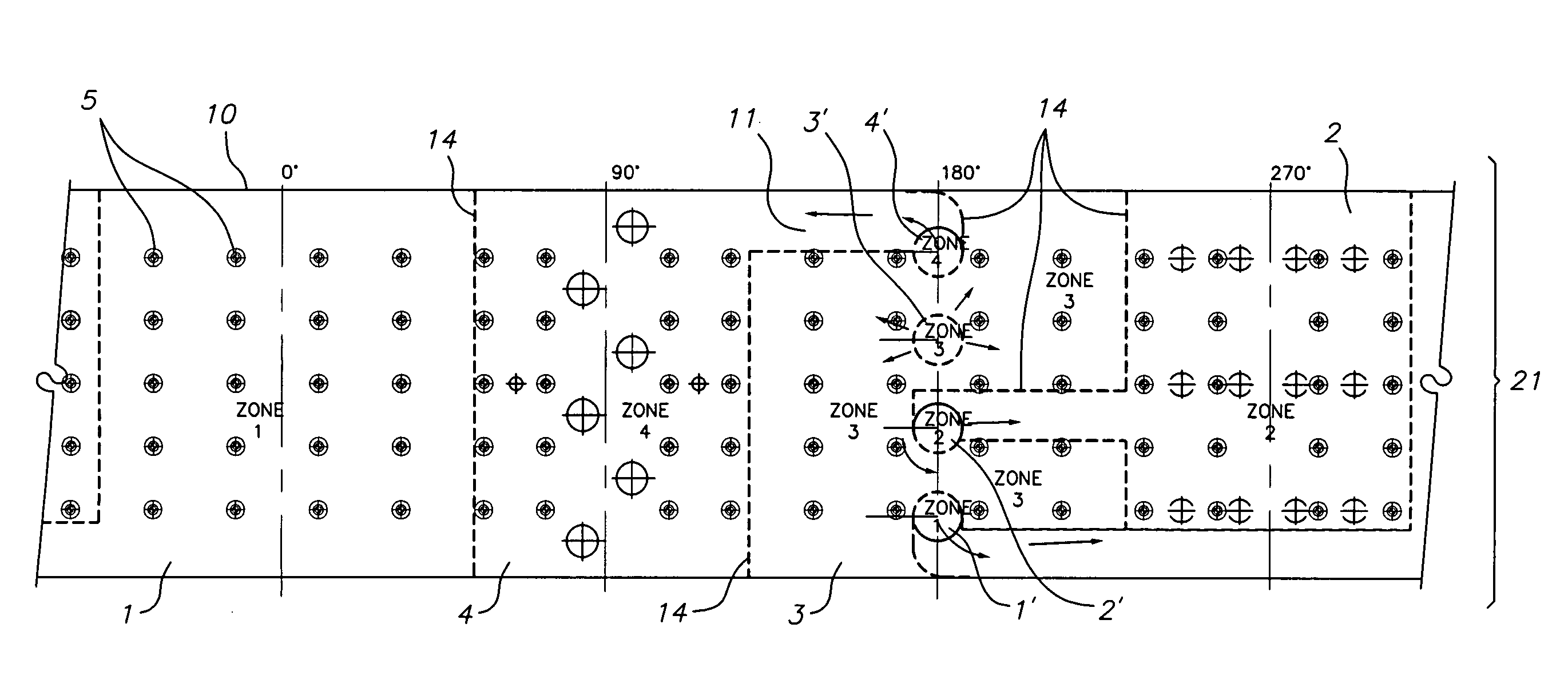
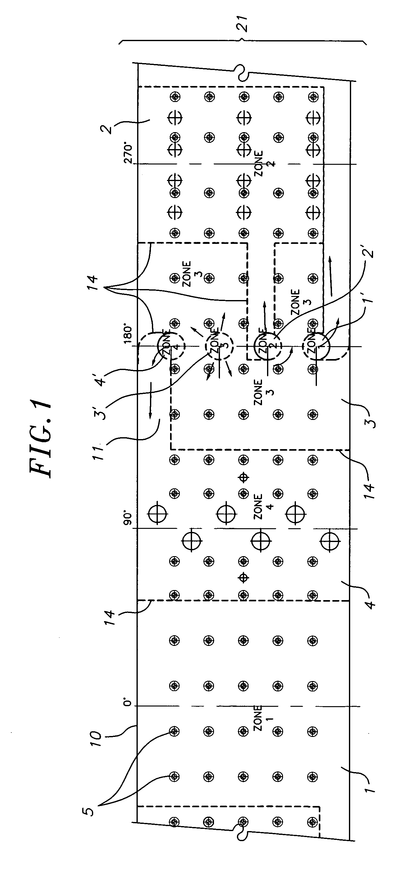
[0034]FIG. 1 is a flat layout of the wall of the inner plenum 10 of the furnace. The plenum contains a series of gas restrictor walls 14 that may, in one embodiment, run perpendicular to the inner wall 21 and outer wall of the plenum and that, in the preferred embodiment, divide the inner chamber of the plenum 10 into four sectors or zones 1, 2, 3, and 4. In alternate embodiments, the inner chamber of the plenum may have any number of zones that best suits the needs of the user.

[0035] For instance, the plenum may be designed to have anywhere between two and eight zones, or it may even have more zones. To further illustrate, if a manufacturer needs to have a level of cooling along the bottom third of the load that is different from the top two-thirds, then a two zone plenum could be manufactured at a cost less expensive than that of a four or eight zone plenum. In manufacturing the plenum, any number of gas restrictor walls 14 can be fixed, such as through welding to the inner wall ...


PUM

PropertyMeasurementUnit
Timeaaaaaaaaaa
Flow rateaaaaaaaaaa
Areaaaaaaaaaaa

Abstract

A vacuum furnace with a gas manifold branching into a plurality of secondary gas manifolds, the secondary gas manifolds each including a valve that is contained in each secondary gas manifold; a hot gas plenum including an inner and an outer shell with the outer shell attached at one side to the secondary gas manifold; a series of gas restrictor walls between the inner and outer shells of the hot gas manifold that serves the purpose of dividing the plenum into a plurality of non-circumferential sectors so that the load in the plenum may be cooled from the top, bottom, left, or right side or any combination thereof.

Description

BACKGROUND OF THE INVENTION [0001] Vacuum furnaces for heat treating, brazing, sintering, and other heat processing generally run cycles with heating ramps that are controlled or uncontrolled to some set point temperature. The parts, load, or work are then cooled down. Cooling modes include vacuum or non-circulated inert gas cooling, forced gas cooling via circulation, controlled cooling, or a combination of different cooling steps. [0002] There are two types of forced circulated inert gas cooling designs commonly used. The first type involves mounting the blower, fan, and motor assembly with heat exchanger internally to the main vacuum vessel. Alternatively, these parts can also be mounted outside of the vacuum chamber via piping connections. Both approaches work; however, the internal type of cooling arrangement tends to require higher and more frequent maintenance due to the proximity of the moving parts to the heated areas. [0003] Further, many loads being cooled in such furnace...

Claims


Application Information

Patent Timeline
IPC IPC(8): F27D15/02
CPCC21D1/613C21D1/667F27B5/16F27D9/00
Inventor JHAWAR, SURESH C.GARCIA, RONALD
Owner G T ENTERPRISES
Why Eureka
Try Eureka