Optical recording medium

a technology of optical recording medium and optical recording medium, which is applied in the direction of photomechanical equipment, instruments, transportation and packaging, etc., can solve the problems of flatness of the resin layer surface damage, and achieve the effects of preventing an increase in cost, minimizing warpage, and excellent surface shap

Inactive Publication Date: 2010-04-13
TDK CORPARATION
View PDF7 Cites 1 Cited by
  • Summary
  • Abstract
  • Description
  • Claims
  • Application Information

AI Technical Summary

Benefits of technology

[0020]Accordingly, it is an object of the invention to provide an optical recording medium capable of forming a resin layer having an excellent surface shape and minimizing a warp while preventing an increase in a cost.

Problems solved by technology

In the case in which a resin layer is formed by using a comparatively coarse screen printing plate, the flatness of the surface of the resin layer is damaged mainly because the entanglement of the resin is caused and bubbles are generated in a coated film of an ultraviolet curing resin on the screen printing plate and are distributed to the vicinity of the surface of the coated film when the ultraviolet curing resin is pushed out.

Method used


Image

  • Optical recording medium
  • Optical recording medium
  • Optical recording medium

Examples


example 1

[0109]A sample #1 was fabricated in the following manner.

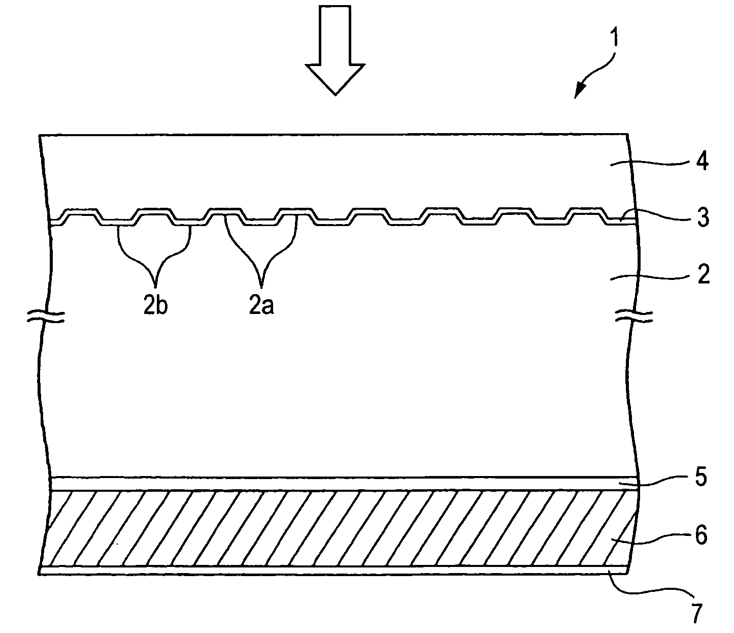
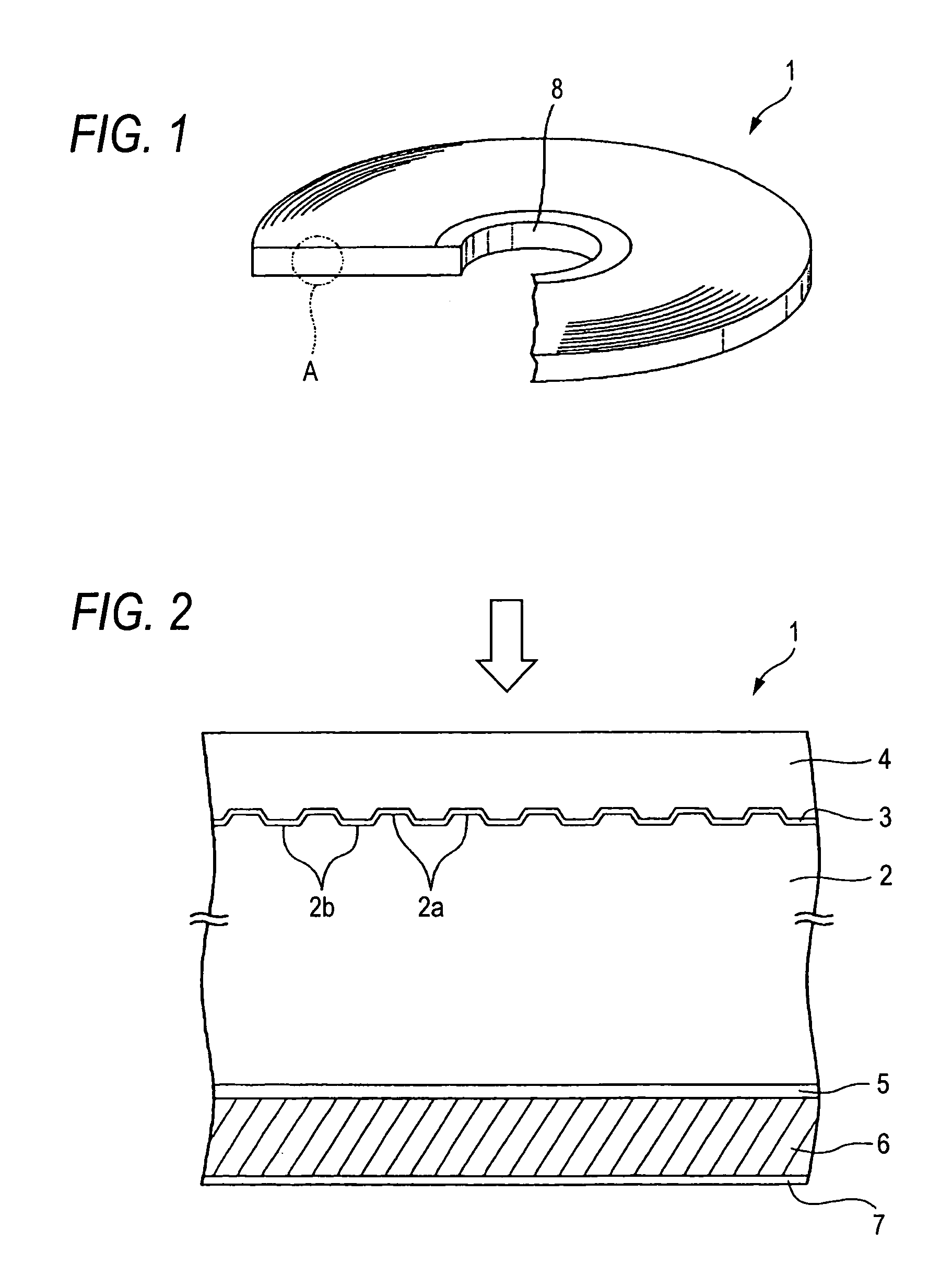
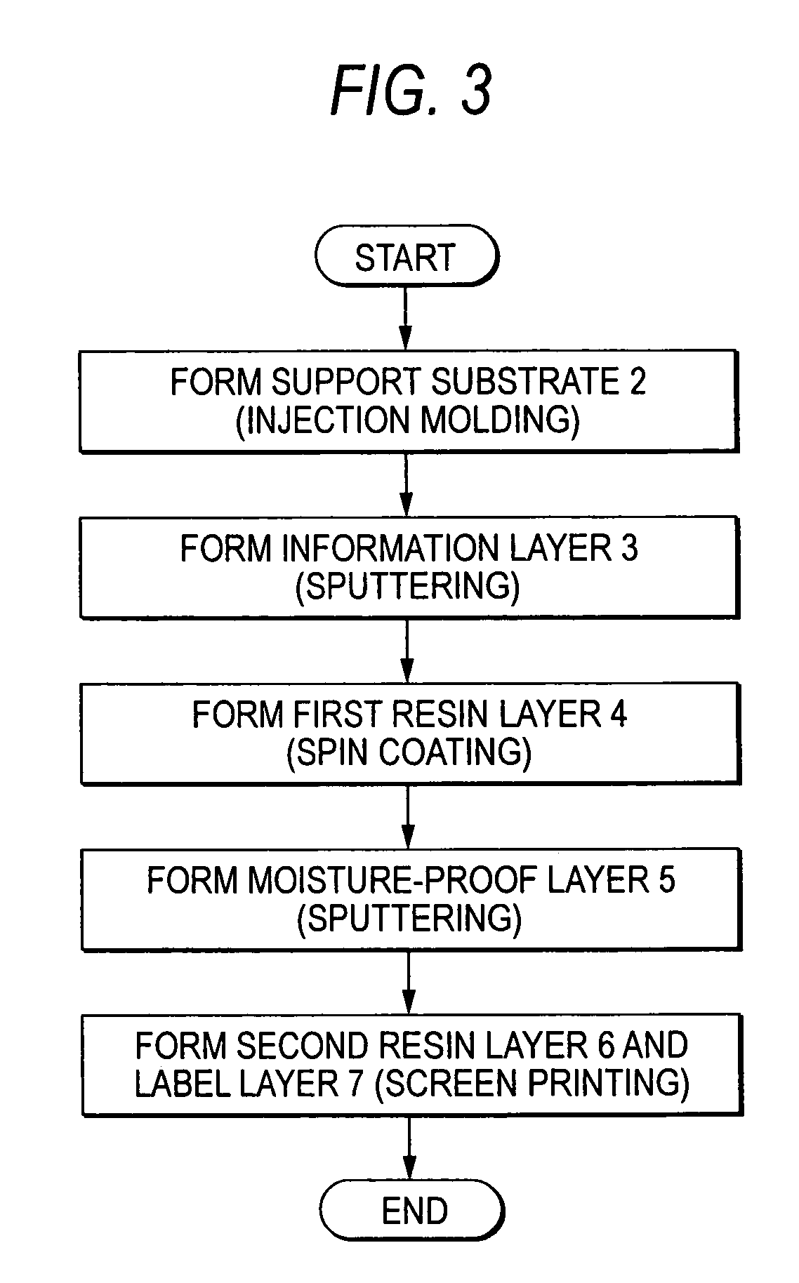
[0110]First of all, a disk-shaped polycarbonate substrate having a thickness of 1.1 mm and an outside diameter of 120 mm was fabricated by injection molding.

[0111]Next, a reflecting film containing Ag as a principal component and having a thickness of 100 nm, a second dielectric film containing a mixture of ZnS and SiO2 and having a thickness of 10 nm, a recording film containing Sb—Te—Ge as a principal component and having a thickness of 10 nm, a first dielectric film containing a mixture of ZnS and SiO2 and having a thickness of 20 nm, and a radiating film containing AIN as a principal component and having a thickness of 30 nm were sequentially formed on the surface of the polycarbonate substrate by sputtering so that an information layer was formed.

[0112]Subsequently, an ultraviolet curing resin A having the following composition was prepared.

[0113]

[Ultraviolet curing resin A]Urethane acrylate (manufactured by Negami Chemic...

example 2

[0136]A sample #6 was fabricated in the following manner.

[0137]First of all, in the same manner as in the sample #1, an information layer and a first resin layer were sequentially formed on one of the surfaces of a polycarbonate substrate, and furthermore, the polycarbonate substrate was turned over to form a moisture-proof layer on the other surface of the polycarbonate substrate.

[0138]Then, 0.5 mass part of a silicon antifoaming agent (manufactured by JUJO CHEMICAL CO., LTD.: trade name “JA-750”) and 1.0 mass part of a non-silicon antifoaming agent (manufactured by Kusumoto Chemicals, Ltd.: trade name of “DISPARLON1951”) were added to the ultraviolet curing resin A and they were stirred for one hour in an environment at a temperature of 50° C.

[0139]Subsequently, the ultraviolet curing resin having the silicon antifoaming agent and the non-silicon antifoaming agent added thereto was applied onto the moisture-proof layer through a screen printing method by utilizing the same screen ...


PUM

PropertyMeasurementUnit
thicknessesaaaaaaaaaa
thicknessaaaaaaaaaa
thicknessaaaaaaaaaa

Abstract

An optical recording medium 1 includes a support substrate 2, an information layer 3 formed on one of the surfaces of the support substrate 2, a first resin layer 4 formed on the information layer 3 and having a thickness of 30 to 200 μm, a moisture-proof layer 5 formed on the other surface of the support substrate 2, a second resin layer 6 formed on the moisture-proof layer 5 and having a thickness of 30 to 200 μm, and a label layer 7 formed on the second resin layer 6, and has such a structure that a laser beam is irradiated through the first resin layer 4. The second resin layer 6 contains 0.5 to 2.8 mass part of a silicon antifoaming agent with respect to 100 mass part of an ultraviolet curing resin, and is formed by a screen printing method.

Description

BACKGROUND OF THE INVENTION[0001]The present invention relates to an optical recording medium, and more particularly to an optical recording medium capable of forming a resin layer having an excellent surface shape and minimizing a warp while preventing an increase in a cost.[0002]Conventionally, optical recording media represented by a CD and a DVD have been utilized widely as recording media for recording digital data. These optical recording media can be classified into read-only optical recording media which can neither once write nor rewrite data, for example, a CD-ROM and a DVD-ROM, write-once optical recording media which can once write data but cannot rewrite data, for example, a CD-R and a DVD-R, and rewritable optical recording media capable of rewriting data, for example, a CD-RW and a DVD-RW.[0003]In order to reproduce data from these optical recording media, a laser beam set to have a power for reproduction is irradiated on the optical recording media and a reflected li...

Claims


Application Information

Patent Timeline
Patent Type & Authority Patents(United States)
IPC IPC(8): B32B3/02G11B7/24G11B7/2403G11B7/254G11B7/257
CPCG11B7/2403G11B7/24067G11B7/252G11B7/2433G11B7/2472Y10T428/21G11B7/2534G11B7/259G11B7/248
Inventor YAMADA, TAKASHIUSHIDA, TOMOKI
Owner TDK CORPARATION
Why Eureka
Try Eureka