
Mid-mount mower

a mower and mid-mount technology, applied in the field of mid-mount mowers, can solve the problems of insufficient depth of the mower deck except the tunnel portion for mulching, difficult to efficiently cut grass clippings into small pieces, and the rear end of the mower deck tends to interfere with the shaft transmission portion, etc., and achieves excellent stability.

Inactive Publication Date: 2005-04-12
KUBOTA LTD
View PDF9 Cites 36 Cited by
  • Summary
  • Abstract
  • Description
  • Claims
  • Application Information

AI Technical Summary

Benefits of technology

This invention has been made having regard to the state of the art noted above, its object is to provide a mid-mount mower for allowing a mower unit to be raised to a large extent without interference between a mower deck and a relay transmission shaft structure connecting a mower input shaft and a PTO shaft, while having a vehicle body of excellent stability with a low center of gravity due to the PTO shaft disposed in a low location.
As the mower deck moves upward, the PTO shaft lowers relative to the mower deck. As a result, the relay transmission shaft and rear universal joint approach the upper surface of the mower deck. However, with the mid-mount mower according to this invention, the recess formed in the rear region of the mower deck is recessed deep to the extent forwardly of the rear universal joint. The rear universal joint is movable into the recess to avoid interference with the mower deck.
Thus, the mower unit may be raised to a large extent without interference between the mower deck and the relay transmission shaft structure connecting the mower input shaft and PTO shaft, while having the vehicle body of excellent stability with a low center of gravity due to the PTO shaft disposed in a low location.
With these features, even where the right and left rear frames extend to a large extent downward in order to lower the rear transmission mechanism for driving the rear wheels, the mower unit may be raised to a large extent without interference between the mower deck and the rear frame pair. As a result, the lawn mower has excellent stability with a low center of gravity due to the rear transmission mechanism disposed in a low location.
To provide a lawn mower of excellent stability with a low center of gravity of the vehicle body, this invention proposes also to place the PTO shaft at a lower level than axles of the rear wheels.

Problems solved by technology

However, the deck except the tunnel portion is insufficient in depth for a mulching operation for cutting the grass clippings into still smaller pieces and depositing them on the ground.
It is difficult to cut the grass clippings into small pieces efficiently by retaining the grass clippings as entrained by rotation of the rotary blades for a sufficiently long time in mulching chambers (enclosures) formed in the mower deck.
Where this mower input shaft and the PTO shaft in the rearward position of the body frame are operatively interconnected through a universal joint and a transmission shaft as in the prior art, the rear end of the mower deck tends to interfere with the shaft transmission portion when the mower unit is raised.
It is difficult to secure a sufficient height for raising the mower unit.
This results in a different inconvenience that the center of gravity of the vehicle body is raised.

Method used


Image

  • Mid-mount mower
  • Mid-mount mower
  • Mid-mount mower

Examples


Embodiment Construction

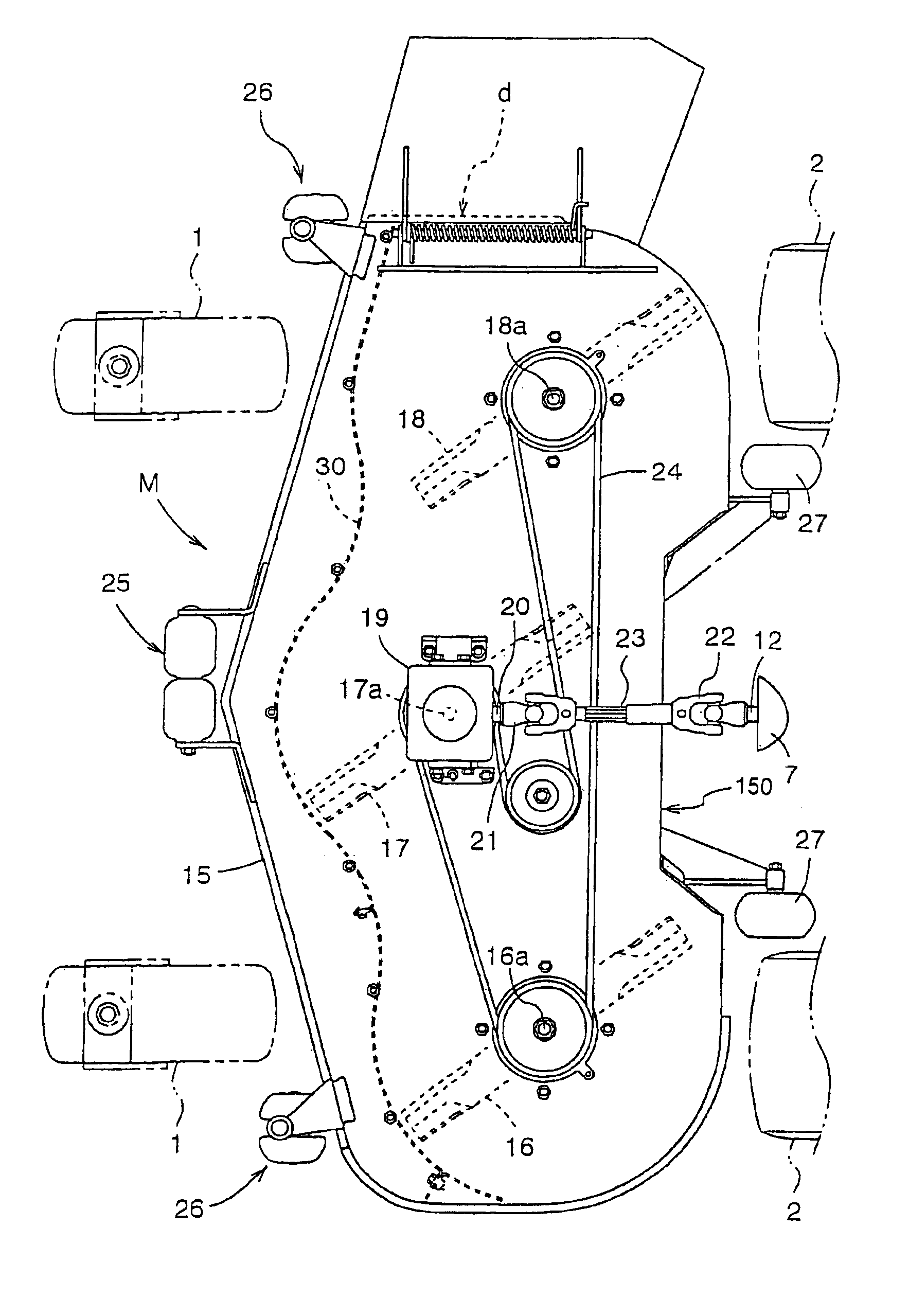
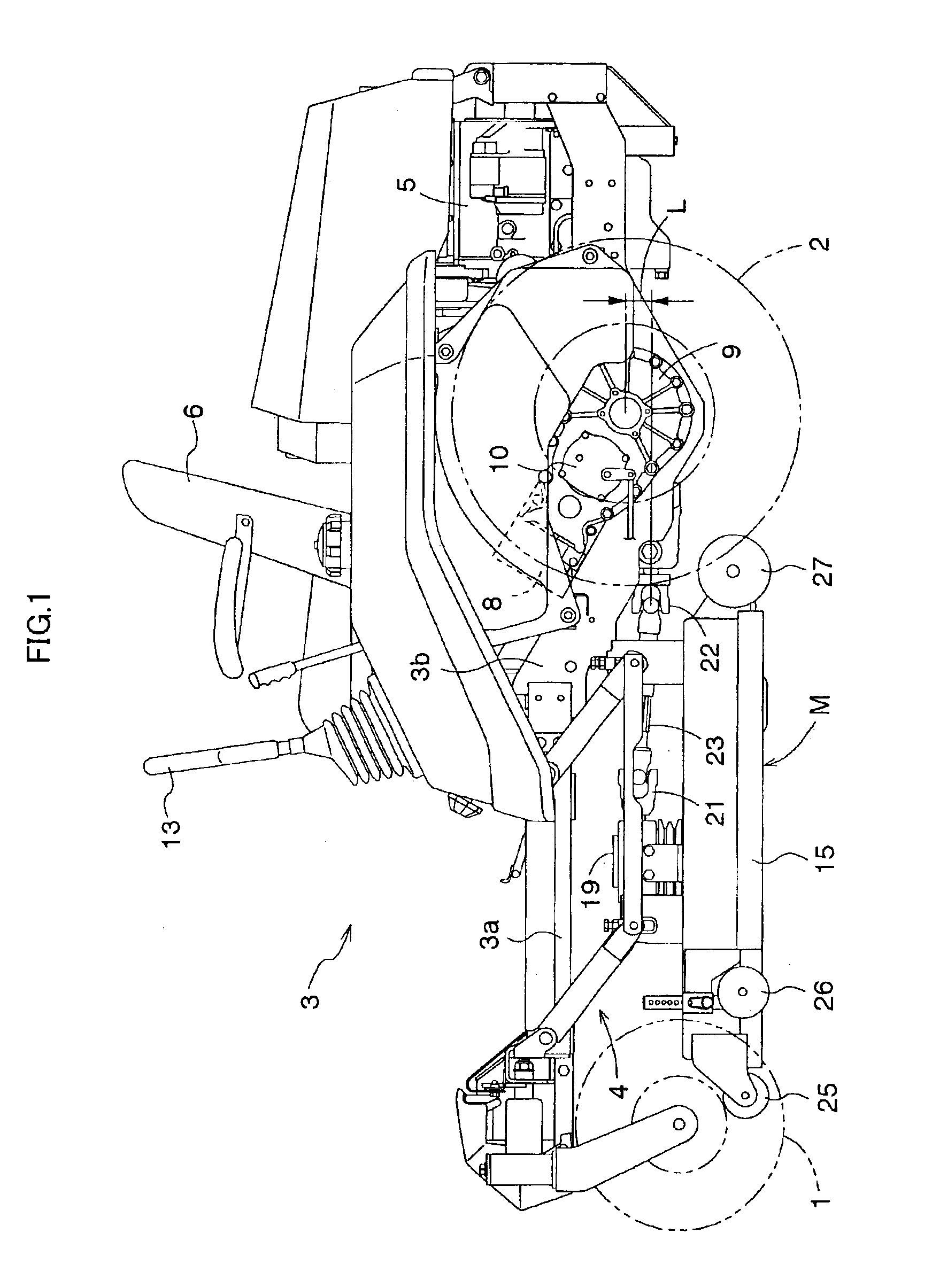
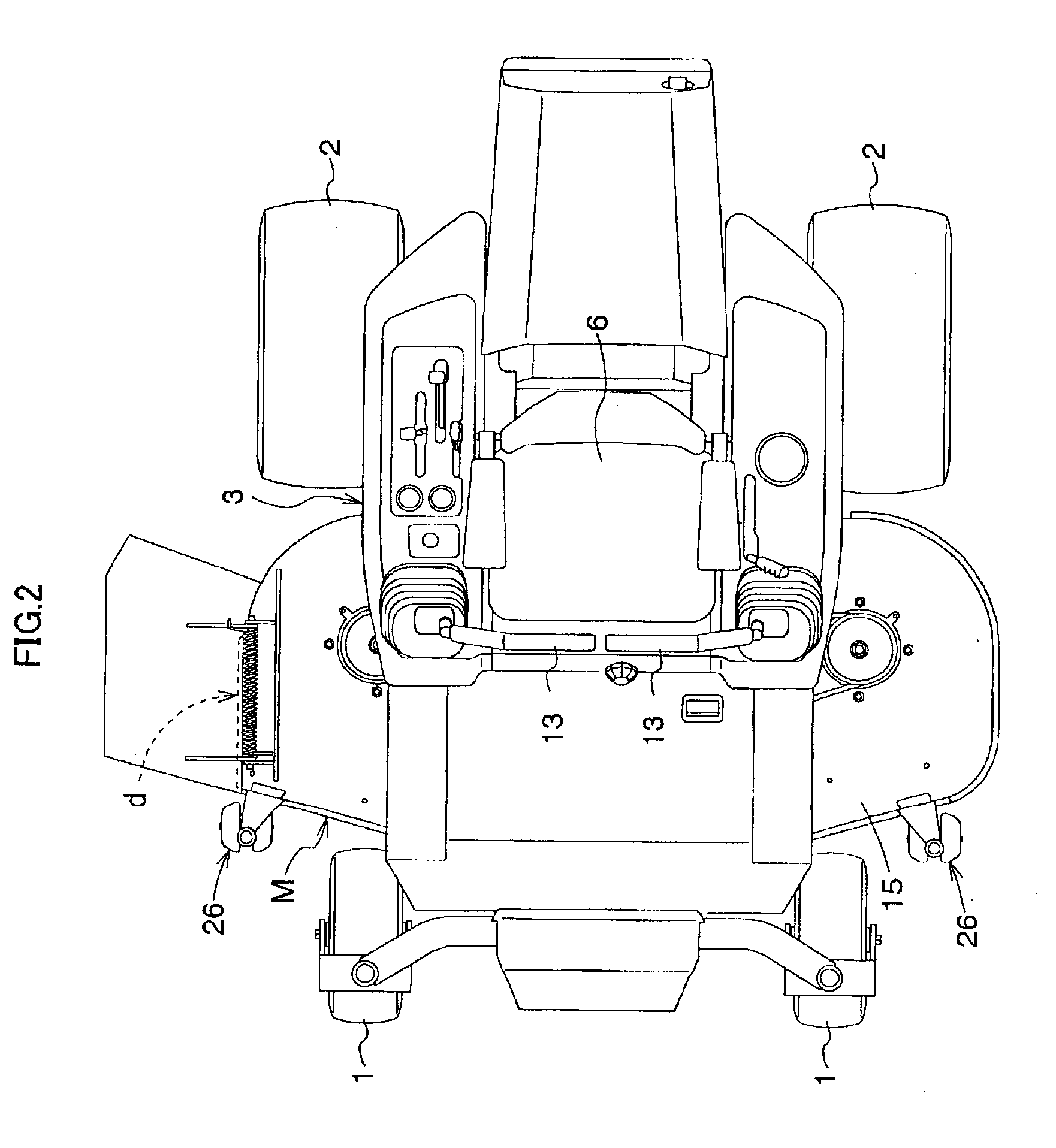
FIG. 1 shows a side elevation of a riding lawn mower which is one example of mid-mount mower according to this invention. FIG. 2 shows a plan view of the mower. This lawn mower includes a pair of right and left front wheels 1 in the form of casters, a pair of right and left drive rear wheels 2, and a vehicle body 3 supported by these wheels. A mower unit M is suspended from the vehicle body 3 between the front and rear wheels by a four-point link mechanism 4. The mower unit M may be moved up and down substantially parallel by vertically moving the link mechanism 4 with hydraulic pressure or manually. An engine 5 is mounted in a rearward position of the vehicle body 3, and a driver's seat 6 disposed forwardly of the engine 5.

As shown in FIGS. 3 and 4, the vehicle body 3 includes a pair of right and left front frames 3a (hereinafter called front frame pair) interconnected by a front cross bar 3c with a large spacing therebetween, and a rear frame pair 3b extending rearward and downwar...


PUM


Abstract

A mid-mount mower including a body frame supported above the ground by front wheels and rear wheels, and a mower unit vertically movably suspended from the body frame between the front wheels and rear wheels. The mower unit includes a mower deck having a top board, and a front wall, side walls and a rear wall depending from the top board. The mower deck has a rearwardly opening recess formed in a sideways middle region at a rear end thereof. A mower input shaft is disposed on the top board for transmitting power to the rotary blades juxtaposed inside the mower deck to be rotatable about three vertical axes arranged sideways. The mower input shaft extends longitudinally of the body frame and has a rear connecting end. A PTO shaft is provided in a rear transmission mechanism that drives the rear wheels. The PTO shaft extends longitudinally of the body frame and has a forward connecting end. A relay transmission shaft has one end thereof connected to the connecting end of the mower input shaft through a front universal joint, and the other end connected to the PTO shaft through a rear universal joint. The recess is recessed longitudinally of the body frame to an extent forwardly of the rear universal joint to receive the rear universal joint when the mower unit is raised.

Description

BACKGROUND OF THE INVENTION1. Field of the InventionThis invention relates to a mid-mount mower having a mower unit vertically movably suspended from a body frame between front wheels and rear wheels. This mower unit has rotary blades rotatable about three vertical axes arranged sideways inside a mower deck, and a mower input shaft disposed on the mower deck to transfer power to the rotary blades. The mower input shaft extends longitudinally of the body frame, and a rear connecting end. The mower input shaft is connected through a universal joint by a relay transmission shaft to a PTO shaft provided in a rear transmission mechanism for driving the rear wheels.2. Description of the Related ArtIn a mower unit attachable to a lawn mower having the above construction, as disclosed in Japanese Patent Publication (Unexamined) No. 2002-67721, for example, the top board of the mower deck has a front portion arched to define a tunnel therein. Grass clippings flying from the front half of the...

Claims


Application Information

Patent Timeline
IPC IPC(8): A01D34/63A01D34/66A01D34/64A01D34/76
CPCA01D34/661Y10S56/22A01D2101/00
Inventor SAMEJIMA, KAZUOCHUJO, KENICHISHIMAMURA, TERUOESAKI, YOSHIYUKIYAMAGUCHI, MASATOSHIKAWAHARA, YOSHIHIRO
Owner KUBOTA LTD
Learn More