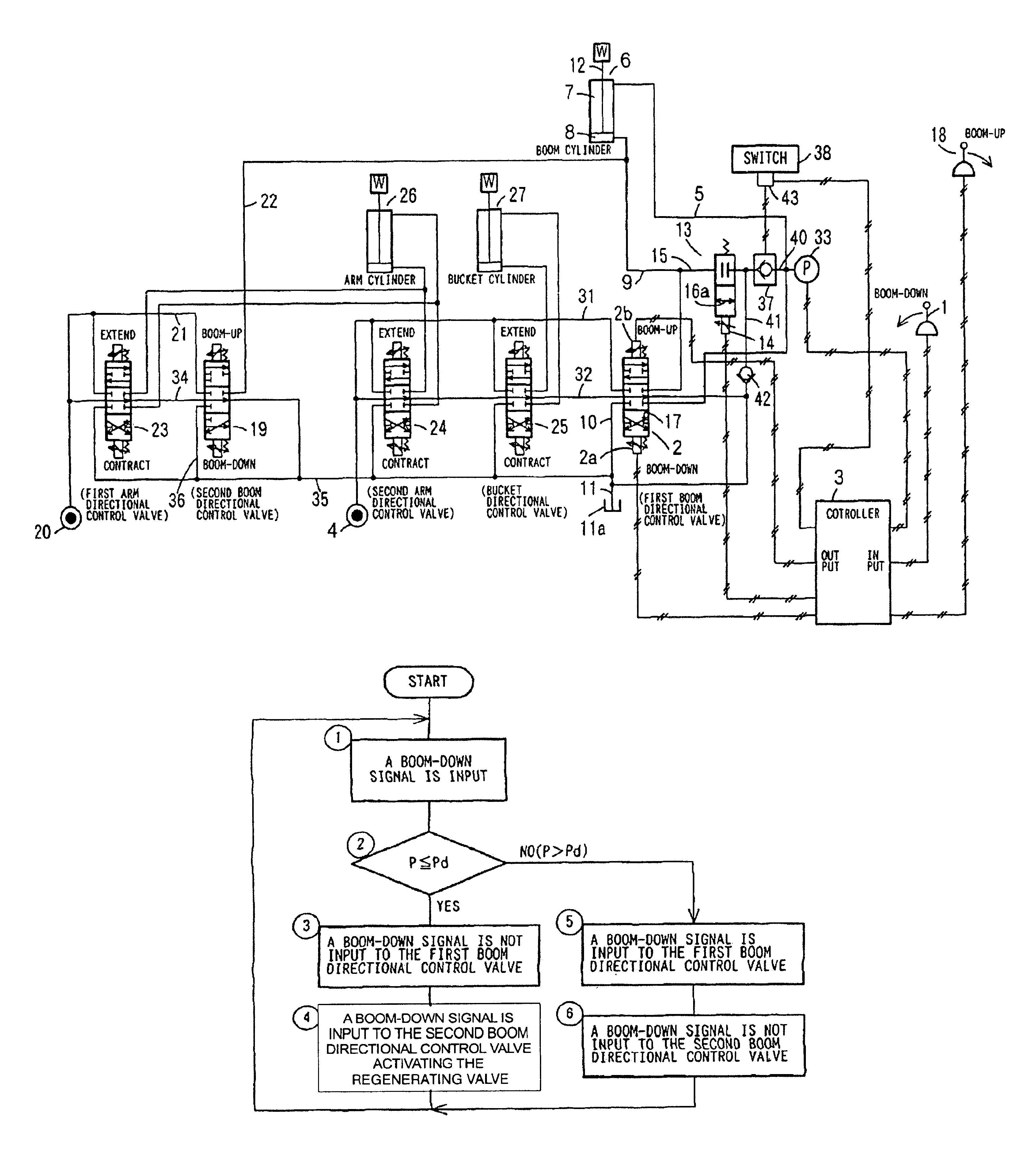
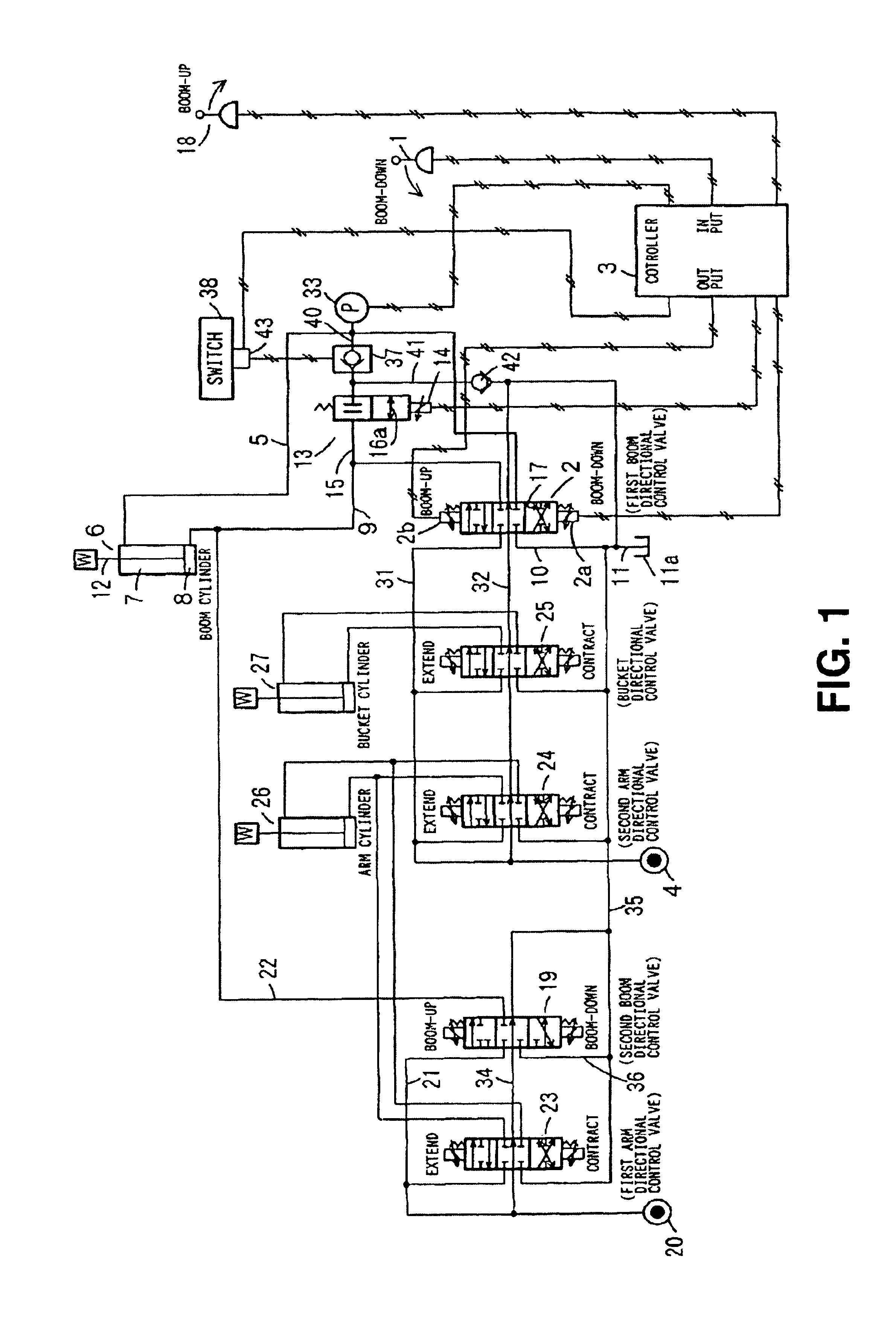
A hydraulic circuit according to the invention includes one directional control valve adapted to receive
hydraulic fluid from a pressurized fluid source and control the direction of the flow of the
hydraulic fluid by shifting the position of said one directional control valve; one hydraulic
actuator adapted to be operated by an external load or
hydraulic fluid, of which the direction of the flow is controlled by the said directional control valve; a regeneration valve for opening or closing off a passage that connects the fluid-returning side and the fluid-feeding side of the aforementioned hydraulic
actuator operated by an external load; a pressure
detector for detecting load pressure applied to the aforementioned hydraulic actuator; at least one other directional control valve adapted to receive hydraulic fluid from the pressurized fluid source and control the direction of the flow of the hydraulic fluid by shifting the position of said other directional control valve(s); at least one other hydraulic actuator adapted to be operated by hydraulic fluid, of which the direction of the flow is controlled by the said other directional control valve; and a controller that is adapted to, upon detecting the load pressure to said one hydraulic actuator to be low by means of said pressure
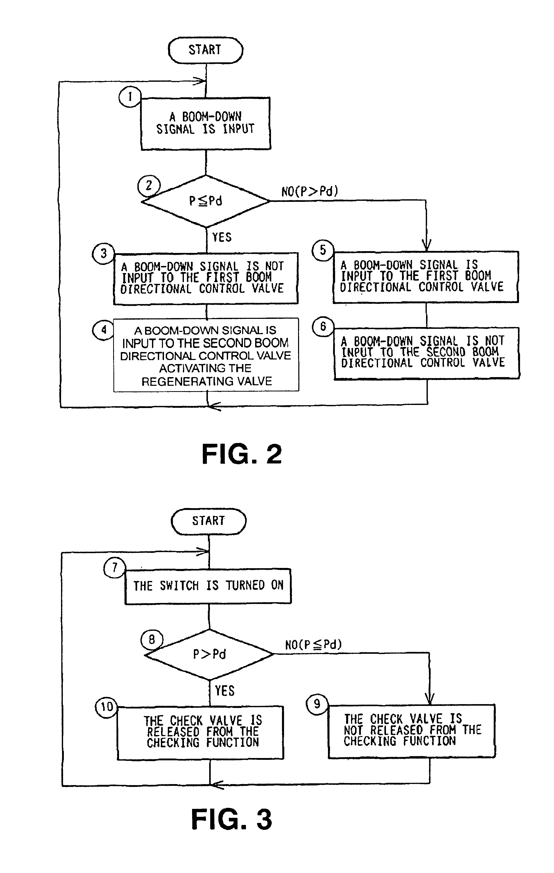
detector, shift said one directional control valve to the
neutral position, thereby interrupting the flow of the hydraulic fluid to said one hydraulic actuator, and simultaneously control the regeneration valve to be open. When operating said one hydraulic actuator by an external load during simultaneous operation of the two hydraulic actuators, the circuit described above enables the hydraulic fluid to be regenerated from the fluid-returning side of the hydraulic actuator through the regeneration valve to the fluid-feeding side of said one hydraulic actuator by controlling said one directional control valve to the
neutral position and the regeneration valve to remain open. Therefore, the hydraulic fluid that can be supplied from the pressurized fluid source to said other hydraulic actuator via said other directional control valve is increased by the amount equivalent to the amount of the hydraulic fluid that is not supplied from the pressurized fluid source to said one hydraulic actuator. As a result, said other hydraulic actuator can work faster in comparison with conventional circuits. The circuit according to the invention thus increases the operating efficiency of the hydraulic
excavator when its hydraulic actuators are operated simultaneously.
According to another feature of the invention, when being at the neutral position, said one directional control valve is capable of discharging into the tank the hydraulic fluid that has been fed from the pressurized fluid source. In cases where said one hydraulic actuator can be actuated by opening the regeneration valve even if said one directional control valve is at the neutral position, the hydraulic fluid fed from the pressurized fluid source to said one directional control valve is discharged to the tank through said one directional control valve, which is at the neutral position. Therefore, the invention is effective in preventing
energy loss that would otherwise occur as a result of unnecessary supply of the hydraulic fluid from the pressurized fluid source to said one hydraulic actuator.
According to yet another feature of the invention, the hydraulic circuit includes yet another directional control valve, which is adapted to receive hydraulic fluid from a pressurized fluid source other than the one mentioned above and shift the position of said yet another directional control valve so that, by shifting to one position, said yet another directional control valve permits the hydraulic fluid fed from the other pressurized fluid source and the hydraulic fluid returned from said one hydraulic actuator to be discharged into the tank and that, by shifting to another position, said yet another directional control valve supplies said one hydraulic actuator with the hydraulic fluid fed from the other pressurized fluid source. By shifting to one position, said yet another directional control valve permits the hydraulic fluid fed from the other pressurized fluid source to be discharged into the tank and also permits the excess hydraulic fluid delivered from said one hydraulic actuator to be discharged into the tank. Therefore, the
energy loss can be reduced. Furthermore, by shifting to the other position, said yet another directional control valve permits the flow of hydraulic fluid supplied from the other pressurized fluid source to join the flow of the hydraulic fluid supplied from said one directional control valve to said one hydraulic actuator, thereby increasing the working speed of said one hydraulic actuator.
According to yet another feature of the invention, said one hydraulic actuator is a boom cylinder for raising or lowering the boom of a front attachment of a hydraulic excavator, and said other hydraulic actuator is a hydraulic actuator or hydraulic actuators other than the boom cylinder of the hydraulic excavator. When lowering the boom by the boom cylinder while simultaneously operating said other hydraulic actuator in the state that the front attachment of the hydraulic excavator is off the ground, there is no need of feeding the hydraulic fluid from the pressurized fluid source to the boom cylinder, and all the hydraulic fluid can be supplied to the other hydraulic actuator. Therefore, the circuit having this feature enables the other hydraulic actuator to move faster in comparison with conventional circuits and consequently offers an increased operation efficiency when operating these actuators simultaneously.
According to yet another feature of the invention, said one hydraulic actuator is a boom cylinder for raising or lowering the boom of a front attachment of a hydraulic excavator; a plurality of hydraulic actuators comprise said other hydraulic actuator, said plurality of hydraulic actuators including at least an arm cylinder for swinging the arm, which is supported at the end of the boom by means of a shaft, and a bucket cylinder for swinging the bucket, which is supported at the end of the arm by means of a shaft; and at least said one directional control valve has a return-oil control orifice adapted to reduce the return oil discharged from the head-side of the boom cylinder into the tank when said one directional control valve is at the boom-down position. When raking in gravel or debris with the bottom of the bucket of a hydraulic excavator in contact with the ground, a conventional circuit requires the operator of the excavator to perform triple combined operation which calls for simultaneously performing boom-up, arm-drawing and bucket-opening. According to the present invention, however, the boom cylinder can extend or contract at will in the axial direction in response to an external force, provided that the regeneration valve is open and that the switch is on. Therefore, gravel or debris can be easily raked in by merely drawing the arm and opening the bucket while pushing the front attachment downward by maintaining said one directional control valve in the boom-down mode. Furthermore, in the course of slope tamping, which calls for hardening the ground by tamping it with the bottom of the bucket by lowering the boom, when the pressure of the hydraulic fluid to the rod-side of the boom cylinder tends to increase with the bucket coming into contact with the ground, the pressure is released to the tank via the
check valve when the switch is on, the regeneration valve in the open state, and the return-oil control orifice of said one directional control valve. Therefore, as an
impact of the bucket with the ground will not produce a boom-down force that is great enough to raise the vehicle, continuous slope tamping can easily be performed.
According to yet another feature of the invention, the controller has a function to control the circuit so that when pressure at the rod-side of the boom cylinder is greater than a given standard pressure, an outside
signal for releasing the
check valve from checking the reverse flow is prevented from being input from the switch to the
check valve even if the switch is turned on. Without this function of the controller, should an outside
signal be input from the switch into the check valve by turning on the switch in the state where there is
high pressure at the rod-side, in other words in the state where the bucket is in contact with the ground with the vehicle body in the raised state as a result of boom-down operation by the boom cylinder, the checking function of the check valve is stopped. Therefore, should the operator unintentionally perform boom-down operation, in other words unintentionally try to further raise the vehicle body, the regeneration valve immediately shifts to the open state so that the hydraulic fluid at the rod-side flows through the check valve and the regeneration valve to the head-side, thereby causing the boom cylinder to extend to extend, resulting in boom-up action and, consequently, causing the vehicle body to fall to the ground. However, the function of the controller to control the check valve as described above is capable of preventing such an accidental falling of the vehicle body.

