Ultrasonic diagnostic apparatus and method for processing ultrasonic signal

a diagnostic apparatus and ultrasonic technology, applied in diagnostics, medical science, instruments, etc., can solve the problems of high apparatus price, limited center frequency of received signal to be imaged, and enlarged apparatus scal

Inactive Publication Date: 2005-04-12
HITACHI LTD
View PDF13 Cites 51 Cited by
  • Summary
  • Abstract
  • Description
  • Claims
  • Application Information

AI Technical Summary

Benefits of technology

The digital ultrasonic diagnostic apparatus according to the invention is characterized in that received

Problems solved by technology

The ultrasonic diagnostic apparatus according to the prior art shown in FIG. 2 has the problem that the frequency of the digital reference signal hn (t) is required to be equalized to the center frequency of the received signal to be imaged and the center frequency of the r

Method used


Image

  • Ultrasonic diagnostic apparatus and method for processing ultrasonic signal
  • Ultrasonic diagnostic apparatus and method for processing ultrasonic signal
  • Ultrasonic diagnostic apparatus and method for processing ultrasonic signal

Examples


first embodiment

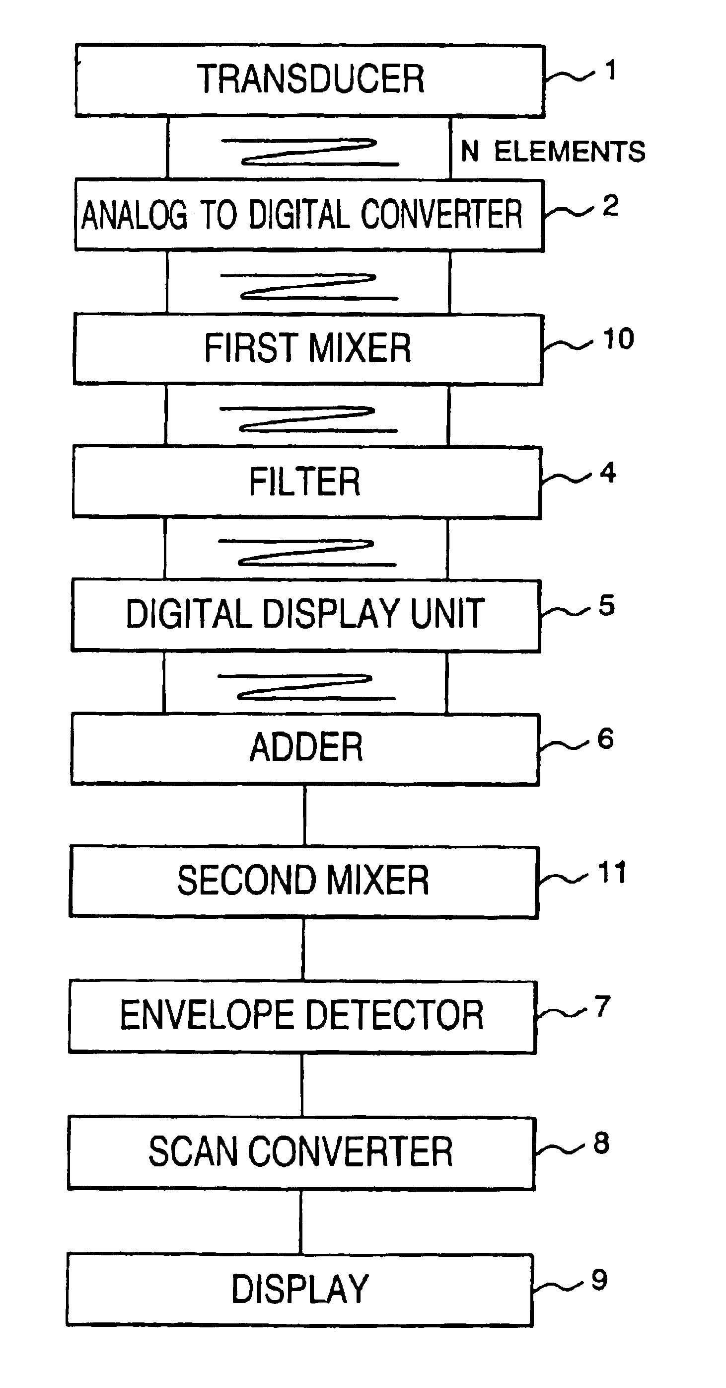
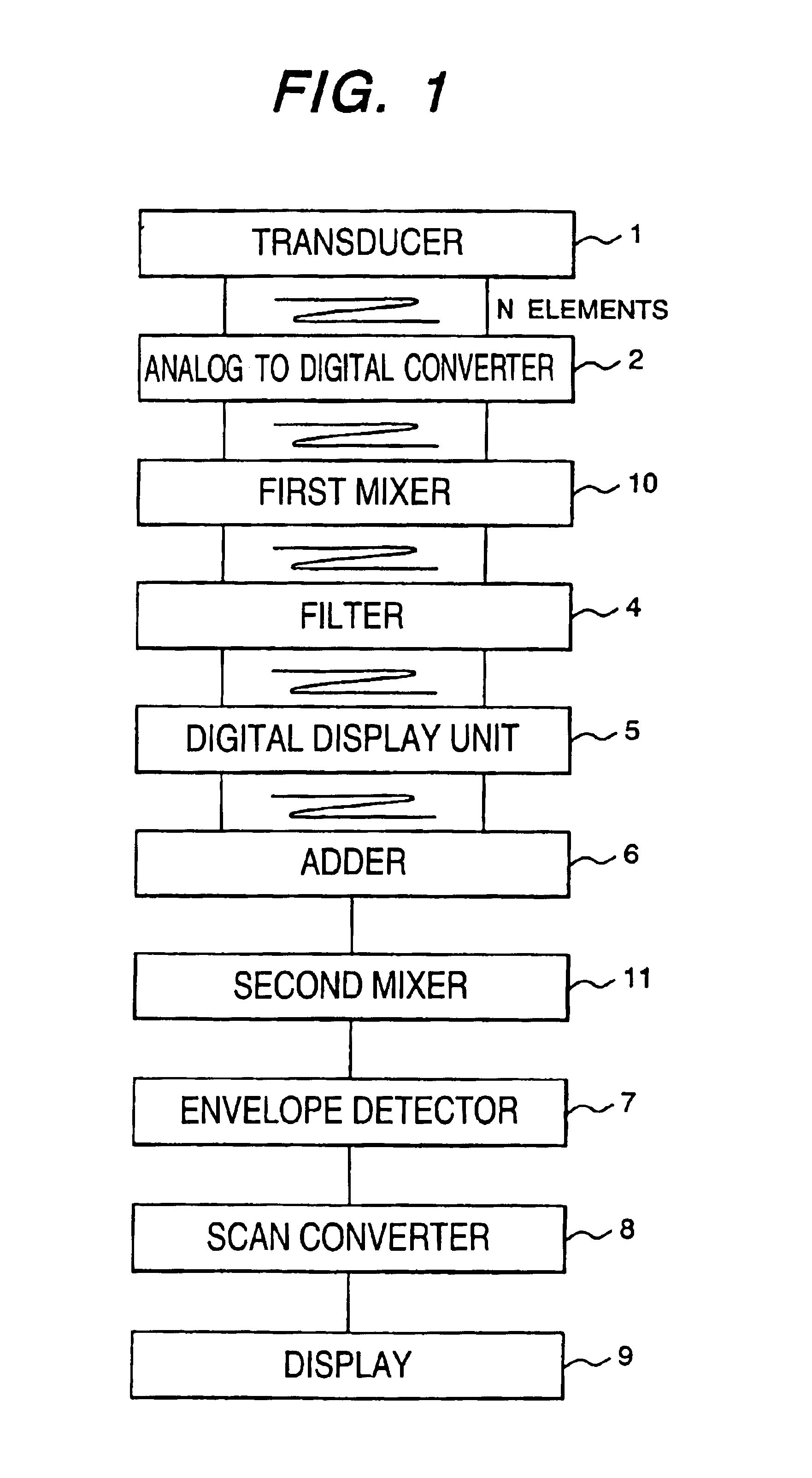
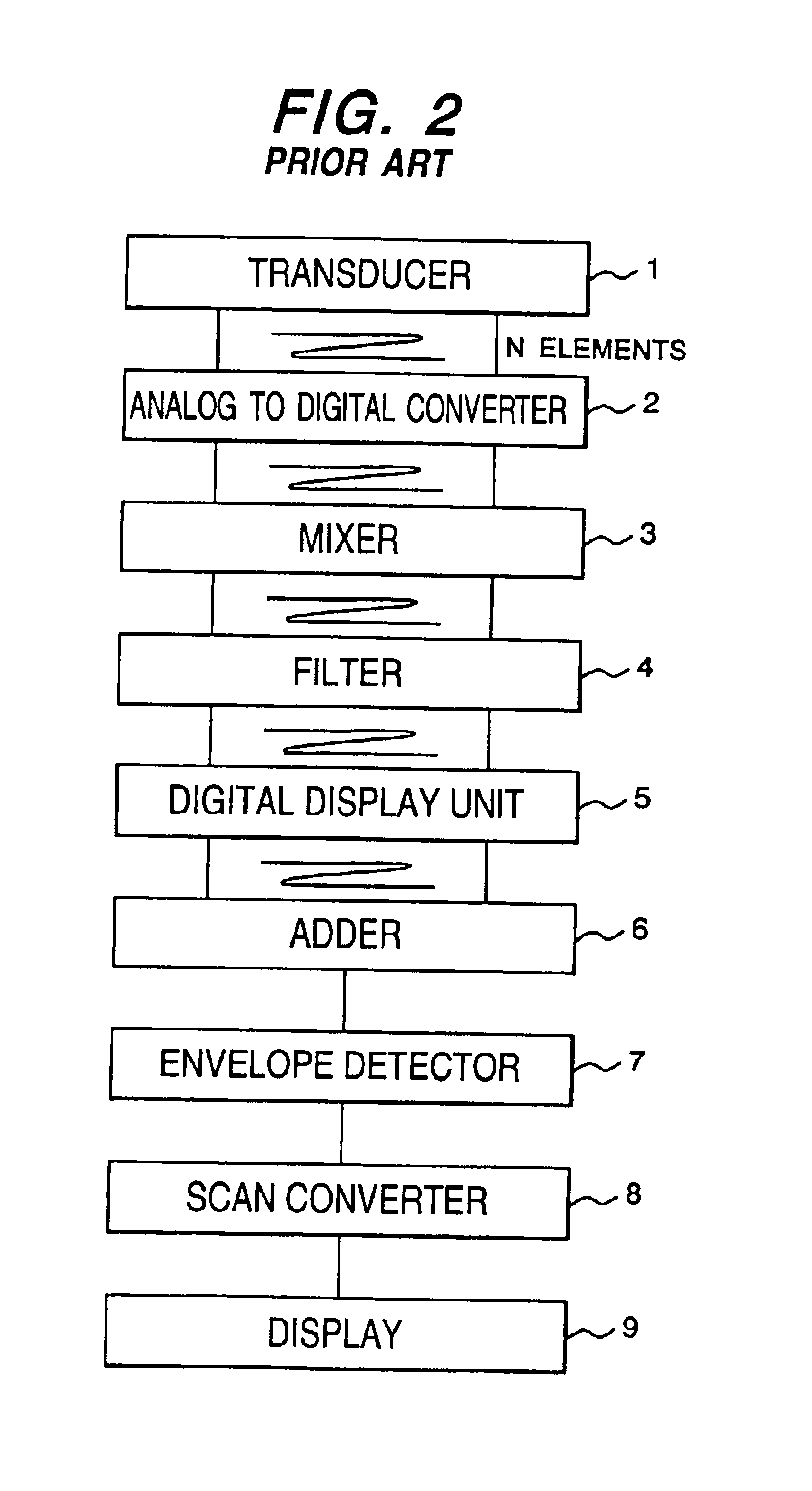
FIG. 1 shows an example of the configuration of an ultrasonic diagnostic apparatus equivalent to the first embodiment of the invention. As shown in FIG. 1, the configuration except the first mixer 10 and the second mixer 11 is the same as the configuration of the ultrasonic diagnostic apparatus according to the prior art shown in FIG. 2. The signal fn (t) received by the “n”th element of the transducer 1 due to an ultrasonic signal s (t) sent from the transducer 1 and having a center frequency ωs is expressed by an expression 8 when propagation delay time from the sending of an ultrasonic wave to the receiving of it is τn as in the expression 2. “φn” denotes a phase of the received signal fn (t) and is expressed by an expression 9 as in the expression 3.

In case the number of elements used for one sending / receiving of an ultrasonic wave is N, N pieces of output signals output from the transducer 1 are respectively expressed by the expression 8. The propagation delay time τn is differ...

second embodiment

FIG. 6 shows an example of the configuration of an ultrasonic diagnostic apparatus equivalent to a second embodiment of the invention. In detail, FIG. 6 shows the example of the configuration of the ultrasonic diagnostic apparatus that simultaneously images and displays plural received signals different in a center frequency without changing each configuration of the analog to digital converter 2, the mixer 3, the filter 4 and the digital delay unit 5 respectively required every channel in the configuration of the ultrasonic diagnostic apparatus shown in FIG. 1.

The configuration of the analog to digital converter 2, the first mixer 10, the filter 4 and the digital delay unit 5 respectively required every channel in the configuration of the ultrasonic diagnostic apparatus shown in FIG. 6 is the same as that of the ultrasonic diagnostic apparatus shown in FIG. 1. The configuration of the ultrasonic diagnostic apparatus shown in FIG. 6 is based upon that of the ultrasonic diagnostic ap...


PUM


Abstract

An ultrasonic diagnostic apparatus acquires images different in a frequency. The invention is composed of a transducer including plural elements for sending an ultrasonic wave and receiving the reflected ultrasonic wave, analog to digital converters that digitize plural received signals, first mixers that respectively multiply a signal from the converter and a first digital reference signal, first filters that respectively extract a signal having a predetermined center frequency from a signal from each first mixer, digital delay units that respectively delay a signal from each first filter, an adder that adds plural signals from the digital delay units, and a second mixer that multiplies a signal from the adder and a second digital reference signal. An envelope detector detects a signal from the second mixer, and a scan converter converts a signal from the detector to a picture signal for display, so the pass band of the filter is not required to be changed.

Description

TECHNICAL FIELDThe present invention relates to an ultrasonic diagnostic apparatus, particularly relates to an ultrasonic diagnostic apparatus for nondestructive inspection that executes processing for converting an ultrasonic signal to a digital signal and an ultrasonic diagnostic apparatus for medicine.BACKGROUND ARTFIG. 2 shows an example of the configuration of an ultrasonic diagnostic apparatus according to prior art using a digital circuit. An ultrasonic signal s (t) sent from a transducer 1 composed of plural elements and having a mean frequency ωs can be approximately expressed by an expression 1. “A (t)” denotes the shape of an envelope of the sent signal, “t” denotes a variable of time and “j” denotes an imaginary unit.s(t)=A(t)×{exp(jωst)+exp(−jωst)}  Expression 1The transducer 1 receives an ultrasonic wave reflected on an object of inspection. A signal fn (t) received by an “n”th element of the transducer 1 is expressed by an expression 2 in case propagation delay time f...

Claims


Application Information

Patent Timeline
IPC IPC(8): G01S15/89G01S15/00G01S7/52A61B8/00
CPCG01S15/895G01S7/52026
Inventor MIWA, YUICHIUMEMURA, SHIN-ICHIROSHINOMURA, RYUICHIBABA, HIROTAKAFUJITA, NAOTO
Owner HITACHI LTD
Why Eureka
Try Eureka