Contoured knee brace frame

a knee brace and frame technology, applied in the field of knee braces, can solve the problems of high risk of knee injuries, many of these knee braces are uncomfortable to wear, and ski and motorcycle racing has proved to be particularly hazardous, and achieve the effect of excellent support for the knee joint and comfortable wear

Inactive Publication Date: 2005-04-12
DJO
View PDF84 Cites 52 Cited by
  • Summary
  • Abstract
  • Description
  • Claims
  • Application Information

AI Technical Summary

Benefits of technology

The preferred embodiments of the present invention provide a new and improved knee brace that provides excellent support to the knee joint while being very comfortable to wear. In a significant feature of the present invention, the knee brace frame is contoured such that no rigid structure is located along the medial superior region of the thigh. As a result, the preferred embodiments of the present invention do not produce pressure along the inner thigh and do not interfere with an opposing knee brace or the natural motion of the leg.
The knee brace frame is generally characterized by upper and lower rigid members that are connected together by polycentric hinges located along the axis of the knee. In a preferred embodiment, the upper rigid member is formed as a single continuous piece that circumvents the medial superior thigh, yet can still be firmly attached to the thigh to provide excellent support and stability of the knee joint.
All the preferred embodiments of the present invention have tremendous structural integrity and can withstand the application of large forces over long periods of time. In addition, the preferred embodiments are easy to assemble and use many parts that are common to knee brace frames that are currently in existence.

Problems solved by technology

Knee injuries are particularly likely to occur during physical activities in which the knees are subjected to significant lateral loads.
Among the numerous physical activities in which knee injuries can occur, skiing and motorcycle racing have proven to be particularly hazardous.
Although various types of preventive knee braces have been proposed, many of these knee braces are uncomfortable to wear during certain physical activities because the rigid upper member of the knee brace presses against the medial superior thigh region of the user's leg.
This discomfort detracts from the enjoyment of the activity and can adversely affect the user's performance.
This is a significant shortcoming since contact between knee braces adversely affects the natural motion of the legs and also produces undesirable noise.
Skiing is an activity in which this problem is particularly troublesome.
The bumps and vibrations experienced while skiing cause the knee braces to impact each other on a continual basis.
This problem is especially apparent while skiing at high speeds, such as during downhill racing, and can significantly impact the skier's performance.
Worse yet, in some cases, it has been found that the knee brace frames can actually catch on each other, thereby causing the skier to fall and possibly resulting in a serious injury.
However, none of the existing knee braces has been sufficient to achieve this goal while still providing adequate support and effectively preventing injuries to the four primary knee ligaments.
Because the rigid frame does not fit snugly onto the leg, the knee joint can move or bend in undesirable directions and can therefore damage the ligaments.
Furthermore, the proposed knee braces have a relatively high profile and are therefore much more likely to catch or snag on a foreign object during physical activity.

Method used


Image

  • Contoured knee brace frame
  • Contoured knee brace frame
  • Contoured knee brace frame

Examples


Embodiment Construction

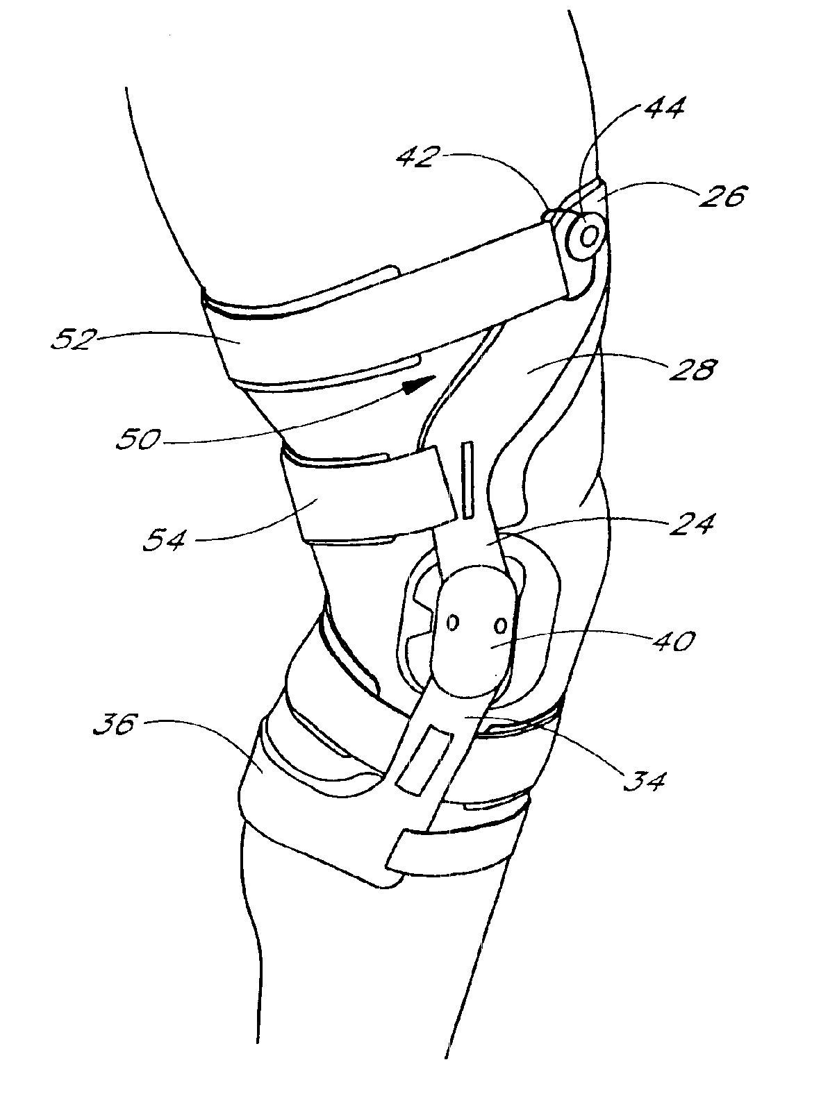
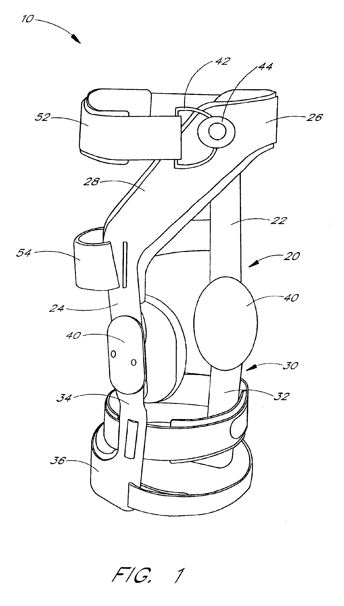
FIG. 1 illustrates a preferred embodiment of a knee brace 10 according to the present invention. The illustrated knee brace 10 is intended for use on the left leg and includes an upper rigid member 20, a lower rigid member 30, and polycentric hinges 40 located along the axis of the knee joint. The knee brace 10 maintains the thigh and calf in proper alignment and thereby prevents injuries caused by lateral knee joint displacement. The polycentric hinges 40 are configured with a limited range of rotation to prevent hyperextension of the lower leg. The knee brace 10 is also provided with a plurality of straps for securing the upper 20 and lower 30 members to the respective thigh and calf portions of the leg. The illustrated knee brace 10 is preferably used to prevent injuries to the knee joint; however, the knee brace may also be used to support the knee joint during rehabilitation after an injury.

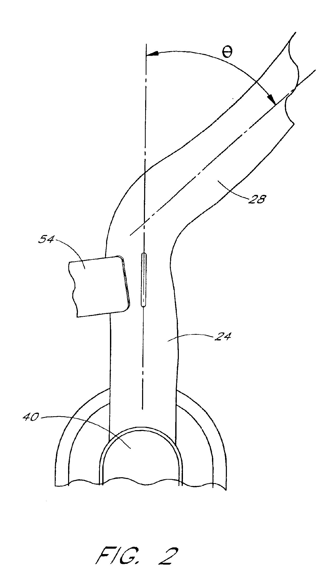
In an important feature of the present invention, the rigid upper member 20 of the knee ...


PUM


Abstract

The present invention provides an improved knee brace that is configured to improve comfort to the user and reduce interference with the natural motion of the user's leg. The knee brace has rigid upper and lower frames that are connected together by polycentric hinges. The rigid upper frame is contoured such that no rigid structure is located along the medial superior region of the thigh. The rigid upper and lower frames are secured to the leg using a plurality of straps.

Description

BACKGROUND OF THE INVENTION1. Field of the InventionThe present invention relates to knee braces. More particularly, the invention relates to a contoured knee brace frame adapted for improved comfort and performance.2. Description of the Related ArtThe human knee generally comprises an articulating joint between the thigh and calf muscle groups that supports the weight of the body while a person is standing, walking or running. The joint is primarily held together by four small but strong ligaments, namely, the anterior and posterior cruciate ligaments and the medial and lateral collateral ligaments. The knee is a relatively weak joint and therefore knee injuries arising out of cartilage damage, ligament strain, and other causes are relatively commonplace. Knee injuries are particularly likely to occur during physical activities in which the knees are subjected to significant lateral loads. Among the numerous physical activities in which knee injuries can occur, skiing and motorcycl...

Claims


Application Information

Patent Timeline
Patent Type & Authority Patents(United States)
IPC IPC(8): A61F5/01A63B71/12
CPCA61F5/0123
Inventor NELSON, KIM ALEXPAULOS, LONNIE E.
Owner DJO
Why Eureka
Try Eureka