High frequency electric motor or generator including magnetic cores formed from thin film soft magnetic material

a technology of soft magnetic material and high frequency electric motor, which is applied in the direction of magnetic circuits characterised by magnetic materials, dynamo-electric machines, etc., can solve the problems of difficult cutting or form, difficult to demonstrate easy manufacturability of motors or generators that include magnetic cores, and inability to take full advantage of the potential of potentially more efficient materials for certain types of applications

Inactive Publication Date: 2005-04-12
GREEN RAY TECH
View PDF8 Cites 43 Cited by
  • Summary
  • Abstract
  • Description
  • Claims
  • Application Information

AI Technical Summary

Problems solved by technology

However, to date it has proved very difficult to provide an easily manufacturable motor or generator that includes magnetic cores formed from thin film soft magnetic materials.
Furthermore, the configurations that have been disclosed to date do not take full advantage of the capabilities of these potentially more efficient materials for certain types of applications.
However, this material is a very hard material making it very difficult to cut or form easily, especially once it has been laminated into a bulk piece.
Also, once annealed to achieve peak magnetic properties, these materials become very brittle.
This makes it difficult and expensive to use the conventional approach to constructing a magnetic core.
Another problem with amorphous metal magnetic cores is that the magnetic permeability of amorphous metal material is reduced when it is subjected to physical stresses.
As an amorphous metal magnetic core is subjected to stresses, the efficiency at which the core directs or focuses magnetic flux is reduced resulting in higher magnetic losses, reduced efficiency, increased heat production, and reduced power.
Although these approaches allow motors and generators to be constructed using amorphous metal cores, there are some inherent problems associated with these approaches.
For example, the use of multiple core pieces to form the overall core means that there are parasitic gaps between adjacent core pieces that the magnetic flux has to cross as the flux flows through the magnetic core.
Although these gaps may be made very small by manufacturing the various core pieces to very tight tolerances, and may be filled with epoxy, they still result in parasitic losses that reduce the efficiency at which the flux can flow through the core compared to a core that does not have these gaps.
In addition to the parasitic gap problem, the methods and arrangements of the '070 and '233 patents make it difficult to always orient the amorphous metal magnetic material in the proper orientation.
In the case of the axial gap configurations disclosed in the '070 and '233 patents, the physical configuration of the axial gap device makes it difficult to maintain the proper air gap between the rotor and the stator.
Because the magnetic forces act axially along the rotational axis of the device, expensive bearings having very tight tolerances must be used to support and hold the rotor in place.
Furthermore, since the stator and rotor supporting members are members that are substantially disk shaped and are generally planar, they are more susceptible to warping or deformation due to the large axial magnetic forces and due to internal stresses caused by temperature changes that occur regularly during normal operation of the device.
As larger and larger axial gap devices are contemplated, the magnetic forces between the rotor and stator become larger and larger further compounding this problem.

Method used


Image

  • High frequency electric motor or generator including magnetic cores formed from thin film soft magnetic material
  • High frequency electric motor or generator including magnetic cores formed from thin film soft magnetic material
  • High frequency electric motor or generator including magnetic cores formed from thin film soft magnetic material

Examples


Embodiment Construction

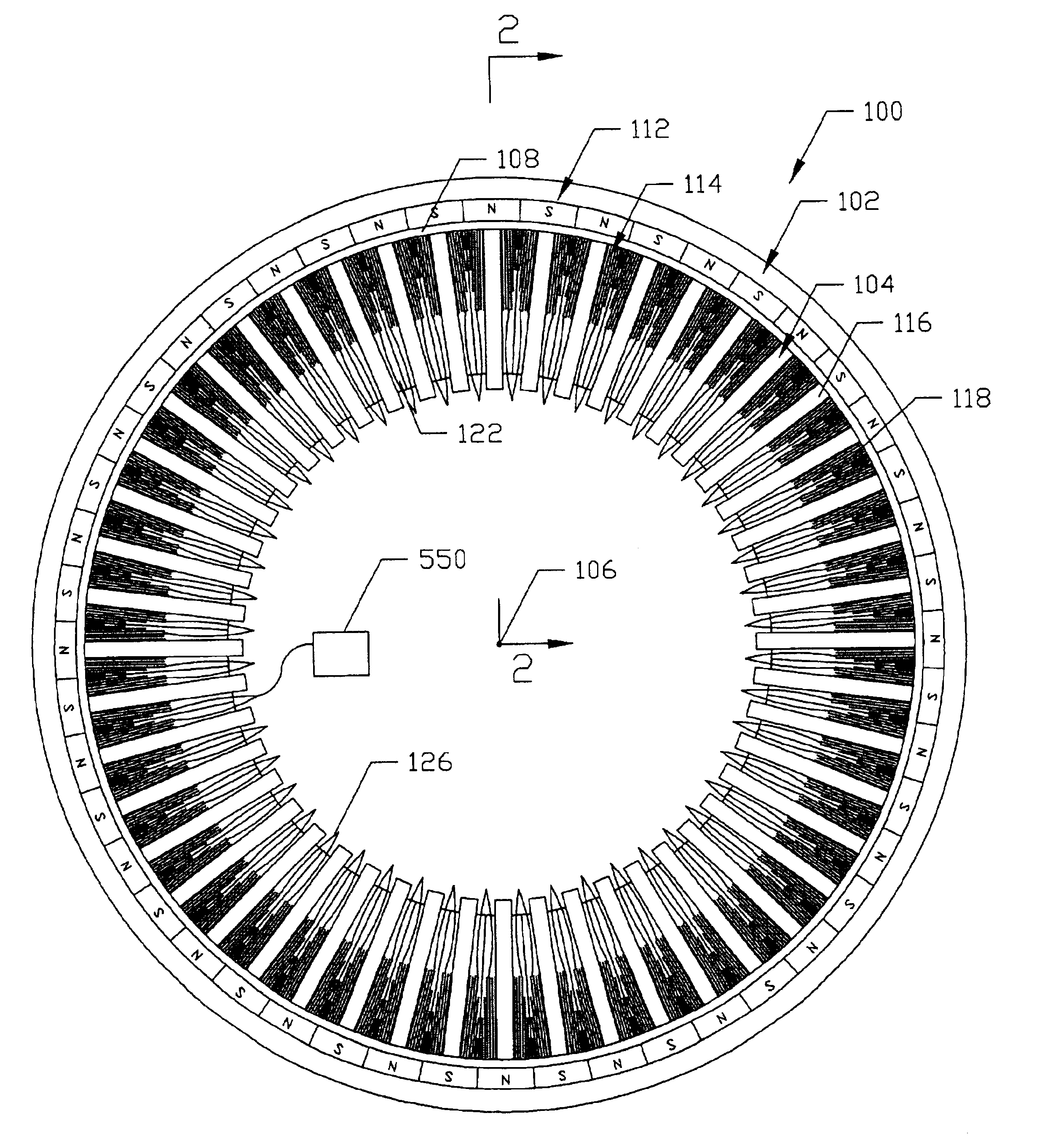
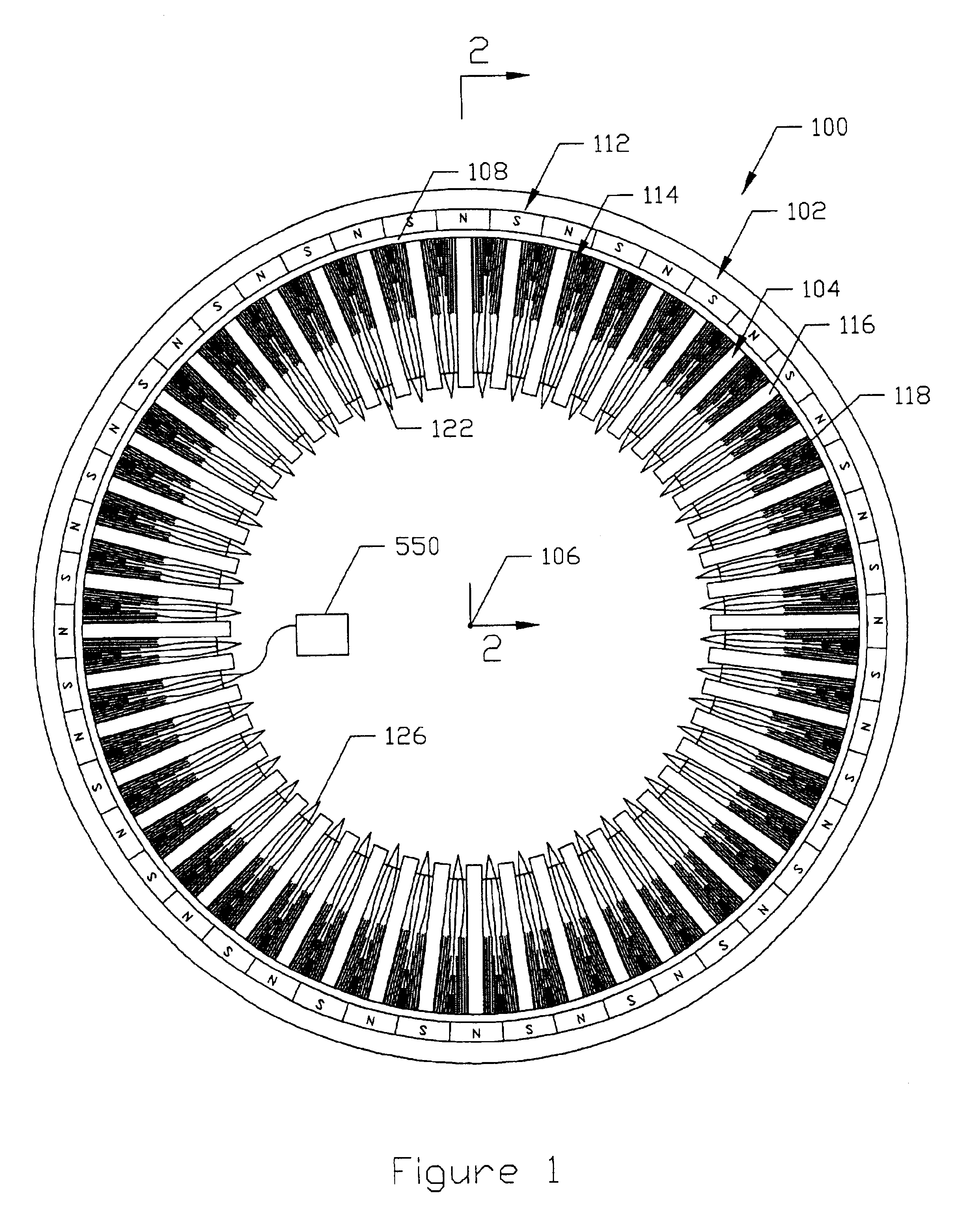
Turning to the drawings, wherein like components are designated by like reference numerals throughout the various figures, attention is initially directed to FIGS. 1 and 2. FIG. 1 illustrates a cross sectional plan view of a device 100 designed in accordance with the present invention. Although device 100 will be referred to as an electric motor or an electric generator at various times throughout this description, it should be understood that device 100 may take the form of a motor, a generator, an alternator, or a regenerative motor depending on the requirements of the application in which the device is used. For purposes of this description, the term regenerative motor refers to a device that may be operated as either an electric motor or an electric generator.

Also, although device 100 will in most cases be described as a DC brushless motor, it should be understood that it may take the form of a wide variety of other types of motors and / or generators and still remain within the s...


PUM


Abstract

A device such as an electric motor, an electric generator, and a regenerative electric motor includes a plurality of independent energizable electromagnetic assemblies. Each independent electromagnetic assembly has an associated one-piece magnetic core formed from thin film soft magnetic material. Each independent electromagnetic assembly defines two stator poles located at opposite ends of the one-piece magnetic core. Each one-piece magnetic core provides the entire magnetic return path for the two opposite magnetic stator poles associated with each independent electromagnetic assembly.

Description

BACKGROUND OF THE INVENTIONThe present invention relates generally to electric motors, generators, and regenerative motors. The term regenerative motor is used herein to refer to a device that may be operated as either an electric motor or a generator. More specifically, the invention relates to an electric motor, generator, or regenerative motor including a stator arrangement which itself includes a plurality of individual electromagnetic assemblies with each independent electromagnetic assembly including an associated one-piece magnetic core formed from thin film soft magnetic material.The electric motor and generator industry is continuously searching for ways to provide motors and generators with increased efficiency and power density. For some time now, it has been believed that motors and generators constructed using permanent super magnet rotors (for example cobalt rare earth magnets and Neodymium-Iron-Boron magnets) and stators including electromagnets with magnetic cores fo...

Claims


Application Information

Patent Timeline
Patent Type & Authority Patents(United States)
IPC IPC(8): H02K1/00H02K1/14H02K1/02H02K21/22H02K29/00
CPCH02K1/02H02K21/22H02K1/141H02K2201/12
Inventor CAAMANO, RAMON A.
Owner GREEN RAY TECH
Why Eureka
Try Eureka