Differential geared turbine engine with torque modulation capability

a technology of torque modulation and which is applied in the direction of engine control, engine fuction, air transportation, etc., can solve the problems of reducing the reliability of aircraft gas turbine engines, and the shaft power transfer system does not offer, disclose or teach differential geared gas turbine engines

Inactive Publication Date: 2005-05-24
PRATT & WHITNEY CANADA CORP
View PDF13 Cites 223 Cited by
  • Summary
  • Abstract
  • Description
  • Claims
  • Application Information

AI Technical Summary

Benefits of technology

[0007]One object of the present invention is to provide a gas turbine engine adapted to modulate engine power distribution between diffe...

Problems solved by technology

These additional stages and the separate power transmitting devices result in weight penalties which are undesirable in aircraft applications.
However, a variable engine flow passage-defining geometry increases the complexity and therefore reduces the reliability of an ...

Method used


Image

  • Differential geared turbine engine with torque modulation capability
  • Differential geared turbine engine with torque modulation capability
  • Differential geared turbine engine with torque modulation capability

Examples


Embodiment Construction

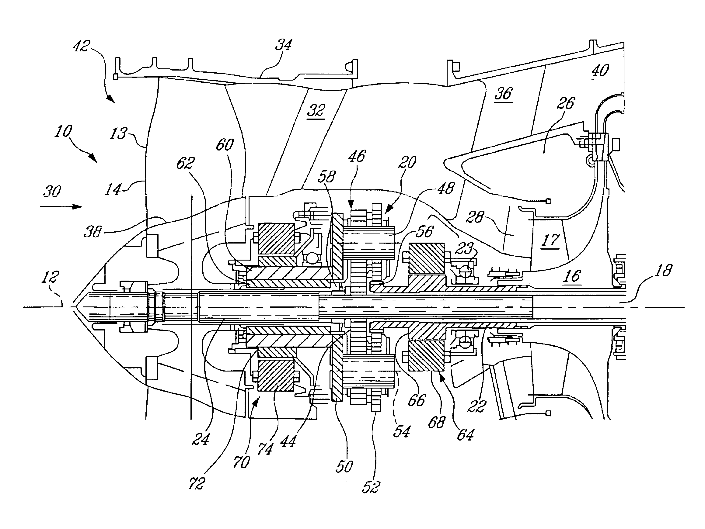
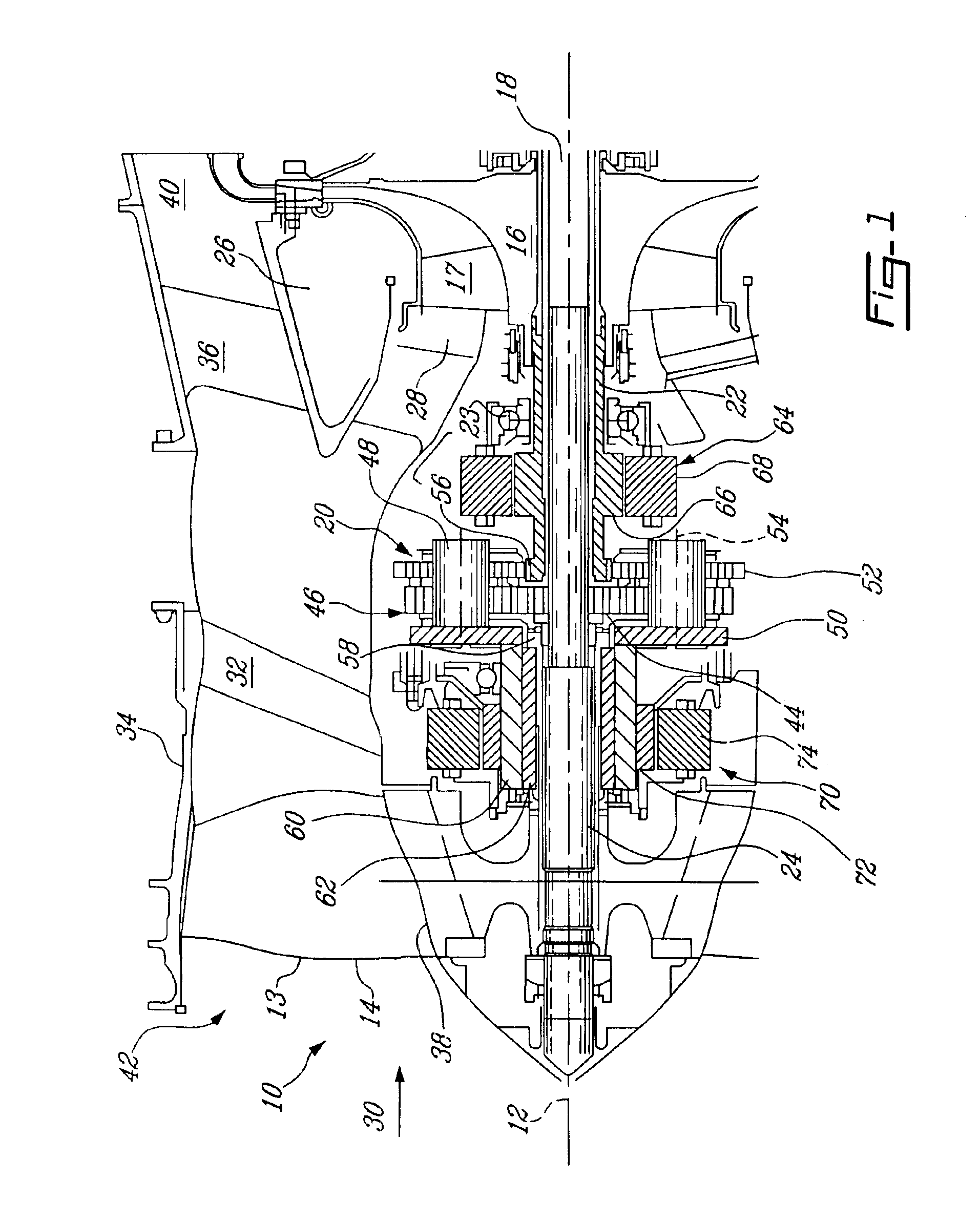
[0016]Referring to the drawings, particularly FIG. 1, an exemplary gas turbine engine 10 includes in serial flow communication about a longitudinal central axis 12, a fan 13 having a plurality of circumferentially spaced apart fan or rotor blades 14, a compressor 16 having a plurality of circumferentially spaced apart compressor blades 17, an annular combustor (not shown), and a turbine (not shown). The turbine includes a rotating shaft 18 extending along the longitudinal central axis 12, and is operatively coupled with a differential gearing system 20. The compressor 16 is coupled to the differential gearing system 20 by a rotor shaft 22 which is rotatably supported by bearing 23 on a stationary structure of the engine 10 and which extends co-axially with respect to the turbine rotating shaft 18. The fan 13 is coupled to the differential gearing system 20 by a rotor shaft 24 extending along the longitudinal central axis 12. Conventional annular combustor (not shown) and fuel inject...


PUM


Abstract

A method and apparatus for controllable distribution of power from a turbine of a gas turbine engine between two rotatable loads of the gas turbine engine, comprises transferring a shaft power of the turbine to the respective rotatable loads using differential gearing operatively coupled with the turbine and the rotatable loads, respectively; and controlling the power transfer using machines operatively coupled with the respective rotatable loads, operable as a generator or a motor for selectively taking power from one of the rotatable loads to drive the other of the rotatable loads, or the reverse.

Description

FIELD OF THE INVENTION[0001]The present invention relates to gas turbine engines, and more particularly, to gas turbine engines in which the power extraction from the compressor and other rotatable loads can be modulated, without affecting turbine operative condition.BACKGROUND OF THE INVENTION[0002]A gas turbine engine generally includes in serial flow communication, one or more compressors followed in turn by a combustor and high and low pressure turbines disposed about a longitudinal axis centerline within an annular outer casing. During operation, the compressors are driven by the respective turbines and compressor air which is mixed with fuel and ignited in the combustor for generating hot combustion gases. The combustion gases flow downstream through the high and low pressure turbines which extract energy therefrom, for driving the compressors, and for producing other output power either as shaft power or thrust for powering an aircraft in flight. For example, in other rotatab...

Claims


Application Information

Patent Timeline
IPC IPC(8): F02C7/32F02C7/36F02C7/00F02K3/00F02K3/02
CPCF01D15/10F02C7/32F02C7/36F05D2270/053Y02T50/671F05D2260/4031F05D2260/40311Y02T50/60F01D25/36F01D15/12
Inventor RAGO, GIUSEPPEHARVEY, RICHARD
Owner PRATT & WHITNEY CANADA CORP
Why Eureka
Try Eureka